Links
Use the Link class to implement a visual relationship between nodes.
See samples that make use of customized Links in the samples index.
Creating Links
Links are normally created by the presence of link data objects in the GraphLinksModel.LinkDataSource or by a parent key reference as the value of the TreeModel.NodeParentKeyProperty of a node data object in a TreeModel. Users can draw new links by using the LinkingTool: Introduction to the Linking Tools.
You can create new links programmatically by modifying the model. It is most common to operate directly on the model by either calling GraphLinksModel.AddLinkData or by calling TreeModel.SetParentKeyForNodeData. Such changes are observed by all diagrams that are displaying the model so that they can automatically create the corresponding Links. You can find examples of calls to GraphLinksModel.AddLinkData in the samples.
It is also possible to create new links without detailed knowledge of the diagram's model by calling LinkingTool.InsertLink. That is how the user's actions to draw a new link actually create it. That method knows how to modify the GraphLinksModel or the TreeModel appropriately, while respecting the additional functionality offered by the LinkingTool.ArchetypeLinkData and other properties of the LinkingTool. You can find examples of calls to LinkingTool.InsertLink in the samples.
Non-directional Links
The simplest links are those without arrowheads to indicate a visual direction. Either the relationship really is non-directional, or the direction is implicit in the organization of the diagram.
The template contains a Shape as the main element, as the line that is drawn between nodes. After the link's route is computed the main Shape will get a Geometry based on the points in the route.
  diagram.NodeTemplate =
    new Node("Auto")
      .Bind("Location", "Loc", Point.Parse)
      .Add(
        new Shape("RoundedRectangle") { Fill = "lightgray" },
        new TextBlock { Margin = 5 }
          .Bind("Text", "Key")
      );

  diagram.LinkTemplate =
    new Link()
      .Add(new Shape());

  diagram.Model =
    new MyModel {
      NodeDataSource = new List<NodeData> {
        new NodeData { Key = "Alpha", Loc = "0 0" },
        new NodeData { Key = "Beta", Loc = "100 50" }
      },
      LinkDataSource = new List<LinkData> {
        new LinkData { From = "Alpha", To = "Beta" }
      }
    };
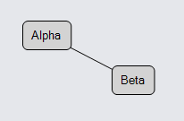
By default the way that the model and diagram know about the node data references of a link data is by looking at its from and to properties. If you want to use different properties on the link data, set GraphLinksModel.LinkFromKeyProperty to be the name of the property that results in the node data's key, and similarly for the GraphLinksModel.LinkToKeyProperty.
Arrowheads
Many links do want to indicate directionality by using arrowheads. GoDiagram makes it easy to create common arrowheads: just add a Shape and set its Shape.ToArrow property. Setting that property will automatically assign a Geometry to the Shape.Geometry and will set other properties so that the arrowhead is positioned at the head of the link and is pointing in the correct direction. Of course you can set the other Shape properties such as Shape.Fill in order to customize the appearance of the arrowhead.
  diagram.NodeTemplate =
    new Node("Auto")
      .Bind("Location", "Loc", Point.Parse)
      .Add(
        new Shape("RoundedRectangle") { Fill = "lightgray" },
        new TextBlock { Margin = 5 }
          .Bind("Text", "Key")
      );

  diagram.LinkTemplate =
    new Link()
      .Add(
        new Shape(),  // the link shape
        new Shape { ToArrow = "OpenTriangle", Fill = null }  // the arrowhead
      );

  diagram.Model =
    new MyModel {
      NodeDataSource = new List<NodeData> {
        new NodeData { Key = "Alpha", Loc = "0 0" },
        new NodeData { Key = "Beta", Loc = "100 50" }
      },
      LinkDataSource = new List<LinkData> {
        new LinkData { From = "Alpha", To = "Beta" }
      }
    };
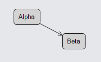
You can see all of the predefined arrowhead types in the Arrowheads Sample.
You can also have an arrowhead at the start of the link: set the Shape.FromArrow property.
Note that an arrowhead normally goes along the path of the link regardless of its position on the path,
so just as with a real arrow, setting { FromArrow = "TripleFeathers" } has the "feathers" pointing forward.
If the link is meant to be bi-directional, the arrowhead name for the "from" end of a link
will probably want to start with the string "Backward...".
Routing
If you want to customize the path that each Link takes, you need to set properties on the link. The property that has the most general effect on the points that the link's route follows is Link.Routing.
This example shows the two most common routing values: LinkRouting.Normal (the default) and LinkRouting.Orthogonal.
  diagram.NodeTemplate =
    new Node("Auto")
      .Bind("Location", "Loc", Point.Parse)
      .Add(
        new Shape("RoundedRectangle") { Fill = "lightgray" },
        new TextBlock { Margin = 5 }
          .Bind("Text", "Key")
      );

  diagram.LinkTemplate =
    new Link()
      .Bind("Routing")
      .Add(
        new Shape(),
        new Shape { ToArrow = "Standard" }
      );

  diagram.Model =
    new MyModel {
      NodeDataSource = new List<NodeData> {
        new NodeData { Key = "Alpha", Loc = "0 0" },
        new NodeData { Key = "Beta", Loc = "50 50" },
        new NodeData { Key = "Gamma", Loc = "100 25" }
      },
      LinkDataSource = new List<LinkData> {
        new LinkData { From = "Alpha", To = "Beta", Routing = LinkRouting.Normal },
        new LinkData { From = "Alpha", To = "Gamma", Routing = LinkRouting.Orthogonal }
      }
    };
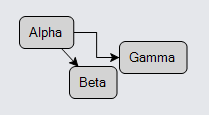
Note that the computed route also depends on the properties of the node, including its shape. There are other properties, including GraphObject.FromSpot and GraphObject.ToSpot, that affect the route. For more discussion about spots, please read this Introduction page: Link Connection Points. Furthermore some Layouts set properties on links to control their routing according to what the layout expects.
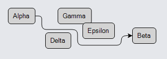
You can also set Link.Routing to LinkRouting.AvoidsNodes:
  diagram.NodeTemplate =
    new Node("Auto")
      .Bind("Location", "Loc", Point.Parse)
      .Add(
        new Shape("RoundedRectangle") { Fill = "lightgray" },
        new TextBlock { Margin = 5 }
          .Bind("Text", "Key")
      );

  diagram.LinkTemplate =
    new Link() { Routing = LinkRouting.AvoidsNodes }
      .Add(
        new Shape(),
        new Shape { ToArrow = "Standard" }
      );

  diagram.Model =
    new MyModel {
      NodeDataSource = new List<NodeData> {
        new NodeData { Key = "Alpha", Loc = "0 0" },
        new NodeData { Key = "Beta", Loc = "250 40" },
        new NodeData { Key = "Gamma", Loc = "100 0" },
        new NodeData { Key = "Delta", Loc = "75 50" },
        new NodeData { Key = "Epsilon", Loc = "150 30" }
      },
      LinkDataSource = new List<LinkData> {
        new LinkData { From = "Alpha", To = "Beta" }
      }
    };
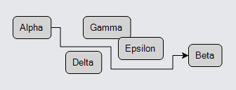
The link's route adjusts to avoid crossing over nodes as nodes are moved around. A small gap between nodes might not be considered wide enough for links to go through.
If a node is very close to or overlaps with either the link's Link.FromNode or Link.ToNode and would block the link's route, it ignores that node, treating it as if it were just an extension of the connected node. Also if no node-avoiding route exists because there is a ring of nodes around one of the connected nodes, the routing algorithm will give up and cross over some nodes anyway.
You can declare that it is OK to route through a node by setting Node.Avoidable to false. This is commonly done for Groups to allow links connecting outside of the group to route nicely within the group.
Note the the use of AvoidsNodes routing is distinctly slower than normal Orthogonal routing, especially for large diagrams.
End Segment Lengths
Another way to affect the precise route that Orthogonal and AvoidsNodes routing take is to set or bind GraphObject.FromEndSegmentLength and GraphObject.ToEndSegmentLength. These properties determine the length of the very first segment or the very last segment, but only for orthogonally routed links. Those properties can be set either on the port element of the node or on the link. On the link the property value takes precedence over the corresponding property's value at the port.
  diagram.NodeTemplate =
    new Node("Auto")
      .Bind("Location", "Loc", Point.Parse)
      .Add(
        new Shape("RoundedRectangle") { Fill = "lightgray" },
        new TextBlock { Margin = 5 }
          .Bind("Text", "Key")
      );

  diagram.LinkTemplate =
    new Link() {
        Routing = LinkRouting.Orthogonal,
        FromSpot = Spot.Left, ToSpot = Spot.Right
      }
      .Bind("FromEndSegmentLength")
      .Bind("ToEndSegmentLength")
      .Add(
        new Shape(),
        new Shape { ToArrow = "Standard" }
      );

  diagram.Model =
    new MyModel {
      NodeDataSource = new List<NodeData> {
        new NodeData { Key = "Alpha", Loc = "0 0" },
        new NodeData { Key = "Beta", Loc = "100 50" },
        new NodeData { Key = "Gamma", Loc = "0 100" },
        new NodeData { Key = "Delta", Loc = "100 150" }
      },
      LinkDataSource = new List<LinkData> {
        new LinkData { From = "Alpha", To = "Beta" },
        new LinkData { From = "Gamma", To = "Delta", FromEndSegmentLength = 4, ToEndSegmentLength = 30 }
      }
    };
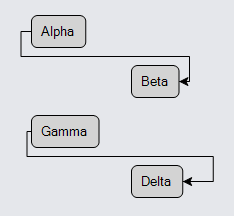
In this example the values of the Link.FromEndSegmentLength and Link.ToEndSegmentLength are bound
to the same named properties on the link data.
In both cases the link's route is forced to come out of the left side of the source node and to the right side of the destination node.
In the case from "Alpha" to "Beta", you see the default behavior.
In the case from "Gamma" to "Delta", you see the results of a shorter-than-normal FromEndSegmentLength
and a longer-than-normal ToEndSegmentLength.
Curve, Curviness, Corner
Once the Link.Routing determines the route (i.e., the sequence of points) that the link takes, other properties control the details of how the link shape gets its path geometry. The first such property is Link.Curve, which controls whether the link shape has basically straight segments or is a big curve.
The default value for Link.Curve is LinkCurve.None, which produces link shapes with straight segments as you see above.
A value of LinkCurve.Bezier produces a naturally curved path for the link shape.
  diagram.NodeTemplate =
    new Node("Auto")
      .Bind("Location", "Loc", Point.Parse)
      .Add(
        new Shape("RoundedRectangle") { Fill = "lightgray" },
        new TextBlock { Margin = 5 }
          .Bind("Text", "Key")
      );

  diagram.LinkTemplate =
    new Link() { Curve = LinkCurve.Bezier }
      .Add(
        new Shape(),
        new Shape { ToArrow = "Standard" }
      );

  diagram.Model =
    new MyModel {
      NodeDataSource = new List<NodeData> {
        new NodeData { Key = "Alpha", Loc = "0 0" },
        new NodeData { Key = "Beta", Loc = "100 50" }
      },
      LinkDataSource = new List<LinkData> {
        new LinkData { From = "Alpha", To = "Beta" }
      }
    };

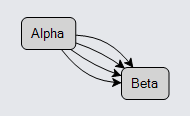
You can control how curved it is by setting the Link.Curviness property. The default produces a slight curve.
If there are multiple links, it will automatically compute reasonable values for the curviness of each link, unless you assign Link.Curviness explicitly.
  diagram.NodeTemplate =
    new Node("Auto")
      .Bind("Location", "Loc", Point.Parse)
      .Add(
        new Shape("RoundedRectangle") { Fill = "lightgray" },
        new TextBlock { Margin = 5 }
          .Bind("Text", "Key")
      );

  diagram.LinkTemplate =
    new Link() { Curve = LinkCurve.Bezier }
      .Add(
        new Shape(),
        new Shape { ToArrow = "Standard" }
      );

  diagram.Model =
    new MyModel {
      NodeDataSource = new List<NodeData> {
        new NodeData { Key = "Alpha", Loc = "0 0" },
        new NodeData { Key = "Beta", Loc = "100 50" }
      },
      LinkDataSource = new List<LinkData> {
        new LinkData { From = "Alpha", To = "Beta" },  // multiple links between the same nodes
        new LinkData { From = "Alpha", To = "Beta" },
        new LinkData { From = "Alpha", To = "Beta" },
        new LinkData { From = "Alpha", To = "Beta" }
      }
    };
Another kind of curviness comes from rounded corners when the Link.Routing is Orthogonal or AvoidsNodes.
  diagram.NodeTemplate =
    new Node("Auto")
      .Bind("Location", "Loc", Point.Parse)
      .Add(
        new Shape("RoundedRectangle") { Fill = "lightgray" },
        new TextBlock { Margin = 5 }
          .Bind("Text", "Key")
      );

  diagram.LinkTemplate =
    new Link() {
        Routing = LinkRouting.AvoidsNodes,
        Corner = 10  // rounded corners
      }
      .Add(
        new Shape(),
        new Shape { ToArrow = "Standard" }
      );

  diagram.Model =
    new MyModel {
      NodeDataSource = new List<NodeData> {
        new NodeData { Key = "Alpha", Loc = "0 0" },
        new NodeData { Key = "Beta", Loc = "250 40" },
        new NodeData { Key = "Gamma", Loc = "100 0" },
        new NodeData { Key = "Delta", Loc = "75 50" },
        new NodeData { Key = "Epsilon", Loc = "150 30" }
      },
      LinkDataSource = new List<LinkData> {
        new LinkData { From = "Alpha", To = "Beta" }
      }
    };
Another kind of curviness comes from setting Link.Curve to LinkCurve.JumpOver. This causes little "hops" in the path of an orthogonal link that crosses another orthogonal link that also has a JumpOver curve.
  diagram.NodeTemplate =
    new Node("Auto")
      .Bind("Location", "Loc", Point.Parse)
      .Add(
        new Shape("RoundedRectangle") { Fill = "lightgray" },
        new TextBlock { Margin = 5 }
          .Bind("Text", "Key")
      );

  diagram.LinkTemplate =
    new Link() {
        Routing = LinkRouting.Orthogonal,  // may be either Orthogonal or AvoidsNodes
        Curve = LinkCurve.JumpOver
      }
      .Add(
        new Shape(),
        new Shape { ToArrow = "Standard" }
      );

  diagram.Model =
    new MyModel {
      NodeDataSource = new List<NodeData> {
        new NodeData { Key = "Alpha", Loc = "0 50" },
        new NodeData { Key = "Beta", Loc = "100 50" },
        new NodeData { Key = "Alpha2", Loc = "50 0" },
        new NodeData { Key = "Beta2", Loc = "50 100" }
      },
      LinkDataSource = new List<LinkData> {
        new LinkData { From = "Alpha", To = "Beta" },  // these two links will cross
        new LinkData { From = "Alpha2", To = "Beta2" }
      }
    };

Note that the use of link jumping is distinctly slower than normal links because all of the crossing points must be computed and the geometry of the link shape will be more complex.
Another kind of curviness (or actually lack of it) comes from setting Link.Curve to LinkCurve.JumpGap. This causes little "gaps" in the path of an orthogonal link that crosses another orthogonal link that also has a JumpGap curve.
  diagram.NodeTemplate =
    new Node("Auto")
      .Bind("Location", "Loc", Point.Parse)
      .Add(
        new Shape("RoundedRectangle") { Fill = "lightgray" },
        new TextBlock { Margin = 5 }
          .Bind("Text", "Key")
      );

  diagram.LinkTemplate =
    new Link() {
        Routing = LinkRouting.Orthogonal,  // may be either Orthogonal or AvoidsNodes
        Curve = LinkCurve.JumpGap
      }
      .Add(
        new Shape(),
        new Shape { ToArrow = "Standard" }
      );

  diagram.Model =
    new MyModel {
      NodeDataSource = new List<NodeData> {
        new NodeData { Key = "Alpha", Loc = "0 50" },
        new NodeData { Key = "Beta", Loc = "100 50" },
        new NodeData { Key = "Alpha2", Loc = "50 0" },
        new NodeData { Key = "Beta2", Loc = "50 100" }
      },
      LinkDataSource = new List<LinkData> {
        new LinkData { From = "Alpha", To = "Beta" },  // these two links will cross
        new LinkData { From = "Alpha2", To = "Beta2" }
      }
    };

Easier Clicking on Links
A problem that users may notice, especially when using fingers but also with the mouse, is that it can be difficult to click on links that have a thin Link.Path. One could set the Shape.StrokeWidth to a larger value, such as 8, but you may not want that appearance.
  diagram.NodeTemplate =
    new Node("Auto")
      .Bind("Location", "Loc", Point.Parse)
      .Add(
        new Shape("RoundedRectangle") { Fill = "lightgray" },
        new TextBlock { Margin = 5 }
          .Bind("Text", "Key")
      );

  diagram.LinkTemplate =
    new Link()
      .Add(
        new Shape() { StrokeWidth = 8 },  // thick path
        new Shape { ToArrow = "Standard" }
      );

  diagram.Model =
    new MyModel {
      NodeDataSource = new List<NodeData> {
        new NodeData { Key = "Alpha", Loc = "0 0" },
        new NodeData { Key = "Beta", Loc = "100 50" }
      },
      LinkDataSource = new List<LinkData> {
        new LinkData { From = "Alpha", To = "Beta" }
      }
    };
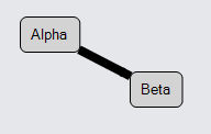
The solution is to add a thick path Shape but not have it draw anything.
This is easily done by setting { Stroke = "transparent", StrokeWidth = 8 }.
However if you want to keep the original path Shape, both Shapes need to be declared as the "main" element
for the Link by setting GraphObject.IsPanelMain to true.
The Link panel knows that all such Shapes should get the same computed Geometry for the link path.
  diagram.NodeTemplate =
    new Node("Auto")
      .Bind("Location", "Loc", Point.Parse)
      .Add(
        new Shape("RoundedRectangle") { Fill = "lightgray" },
        new TextBlock { Margin = 5 }
          .Bind("Text", "Key")
      );

  diagram.LinkTemplate =
    new Link()
      .Add(
        new Shape() { IsPanelMain = true, Stroke = "transparent", StrokeWidth = 8 },  // thick undrawn path
        new Shape() { IsPanelMain = true },  // default Stroke == "black", StrokeWidth == 1
        new Shape { ToArrow = "Standard" }
      );

  diagram.Model =
    new MyModel {
      NodeDataSource = new List<NodeData> {
        new NodeData { Key = "Alpha", Loc = "0 0" },
        new NodeData { Key = "Beta", Loc = "100 50" }
      },
      LinkDataSource = new List<LinkData> {
        new LinkData { From = "Alpha", To = "Beta" }
      }
    };
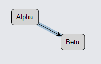
This will make it easier to select the link than without the second transparent link path shape.
The transparent shape can also be used for highlighting purposes. For example, to implement the effect of highlighting the link when the mouse passes over it, add GraphObject.MouseEnter and GraphObject.MouseLeave event handlers:
  diagram.NodeTemplate =
    new Node("Auto")
      .Bind("Location", "Loc", Point.Parse)
      .Add(
        new Shape("RoundedRectangle") { Fill = "lightgray" },
        new TextBlock { Margin = 5 }
          .Bind("Text", "Key")
      );

  diagram.LinkTemplate =
    new Link() {
        MouseEnter = (e, l, _) => { ((l as Link).Elt(0) as Shape).Stroke = "rgba(0,90,156,.3)"; },
        MouseLeave = (e, l, _) => { ((l as Link).Elt(0) as Shape).Stroke = "transparent"; }
      }
      .Add(
        new Shape() { IsPanelMain = true, Stroke = "transparent", StrokeWidth = 8 },  // thick undrawn path
        new Shape() { IsPanelMain = true },  // default Stroke == "black", StrokeWidth == 1
        new Shape { ToArrow = "Standard" }
      );

  diagram.Model =
    new MyModel {
      NodeDataSource = new List<NodeData> {
        new NodeData { Key = "Alpha", Loc = "0 0" },
        new NodeData { Key = "Beta", Loc = "100 50" }
      },
      LinkDataSource = new List<LinkData> {
        new LinkData { From = "Alpha", To = "Beta" }
      }
    };
Short Lengths
Note in the example above with the thick black path shape, that the arrowhead seems to have disappeared due to the thickness of the link path. One can avoid the problem by increasing the GraphObject.Scale of the arrowhead, perhaps to 2.
  diagram.NodeTemplate =
    new Node("Auto")
      .Bind("Location", "Loc", Point.Parse)
      .Add(
        new Shape("RoundedRectangle") { Fill = "lightgray" },
        new TextBlock { Margin = 5 }
          .Bind("Text", "Key")
      );

  diagram.LinkTemplate =
    new Link()
      .Add(
        new Shape() { StrokeWidth = 8 },  // thick path
        new Shape { ToArrow = "Standard", Scale = 2 }  // bigger arrowhead
      );

  diagram.Model =
    new MyModel {
      NodeDataSource = new List<NodeData> {
        new NodeData { Key = "Alpha", Loc = "0 0" },
        new NodeData { Key = "Beta", Loc = "100 50" }
      },
      LinkDataSource = new List<LinkData> {
        new LinkData { From = "Alpha", To = "Beta" }
      }
    };
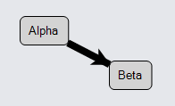
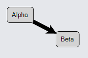
Now the arrowhead is clearly visible. But that in turn shows that the arrowhead is still obscured at the very end of the link path, where it is too wide to show the point of the arrowhead. That problem can be avoided by setting Link.ToShortLength to a value such as 8, depending on the kind of arrowhead used. The path geometry will be shortened by that distance so that the link path does not interfere with the arrowhead.
  diagram.NodeTemplate =
    new Node("Auto")
      .Bind("Location", "Loc", Point.Parse)
      .Add(
        new Shape("RoundedRectangle") { Fill = "lightgray" },
        new TextBlock { Margin = 5 }
          .Bind("Text", "Key")
      );

  diagram.LinkTemplate =
    new Link() { ToShortLength = 8 }  // shortens path to avoid interfering with arrowhead
      .Add(
        new Shape() { StrokeWidth = 8 },  // thick path
        new Shape { ToArrow = "Standard", Scale = 2 }  // bigger arrowhead
      );

  diagram.Model =
    new MyModel {
      NodeDataSource = new List<NodeData> {
        new NodeData { Key = "Alpha", Loc = "0 0" },
        new NodeData { Key = "Beta", Loc = "100 50" }
      },
      LinkDataSource = new List<LinkData> {
        new LinkData { From = "Alpha", To = "Beta" }
      }
    };
There is also a Link.FromShortLength property, to control how far the "from" end of the link path is drawn. If there is an end segment, the distance that it can be shortened is limited to the corresponding Link.ToEndSegmentLength or Link.FromEndSegmentLength. Note also that the short length may be negative, which would cause the link path to be drawn longer -- into the port at which the link is connected.
Disconnected Links
The normal expectation is that one cannot have a link relationship unless it connects two nodes. However GoDiagram does support the creation and manipulation of links that have either or both of the Link.FromNode and Link.ToNode properties with null values. This is demonstrated by the Draggable Link sample.
Both ends of the link must be connected to nodes in order for the standard link routing to operate. If a link does not know where to start or where to end, it cannot compute a route or a position for the link. However, you can provide a route by setting or binding Link.Points to a list of two or more Points. That will automatically give the link a position so that it can be seen in the diagram.
The linking tools, LinkingTool and RelinkingTool, normally do not permit the creation or reconnection of links that connect with "nothing". However, you can set LinkingBaseTool.IsUnconnectedLinkValid to true to allow the user to do so, as the Draggable Link sample demonstrates.
Links cannot normally be dragged unless they are part of a collection that includes the connected nodes. However, you can set DraggingTool.DragsLink to true to allow the user to drag a solitary Link. This mode allows the user to disconnect a link by dragging it away from the node(s)/port(s) to which it was attached. It also allows the user to reconnect one or both ends of the link by dropping it so that the end(s) are at valid port(s). This too is demonstrated by the Draggable Link sample.