Get Started with GoDiagram
GoDiagram Tutorials
GoDiagram is a .NET library for implementing interactive diagrams. This page will show you the essentials of using GoDiagram. We assume you are a programmer who is familiar with C#, .NET, and WinForms.
First, let's load the GoDiagram library. We recommend referencing the library via NuGet:
<PackageReference Include="Northwoods.GoDiagram.WinForms" Version="x.y.z" />
You can download GoDiagram and all the samples from here.
Each GoDiagram diagram is contained in a control in your form:
  // Form1.Designer.cs
  ...
  private void InitializeComponent() {
    ...
    this.diagramControl1 = new Northwoods.Go.WinForms.DiagramControl();

    this.diagramControl1.BackColor = System.Drawing.Color.LightGray;
    this.diagramControl1.Location = new System.Drawing.Point(3, 3);
    this.diagramControl1.Name = "diagramControl1";
    this.diagramControl1.Size = new System.Drawing.Size(400, 150);
  }
  ...
  private Northwoods.Go.WinForms.DiagramControl diagramControl1;
This creates an empty diagram:
This article will show you by example how to build GoDiagram objects. For more detail, read Building Objects in GoDiagram.
Diagrams and Models
The Nodes and Links of a Diagram are visualizations of data that is managed by a Model. GoDiagram has a model-view architecture, where Models hold the data (collections of objects) that describe nodes and links, and Diagrams act as views to visualize this data using actual Node and Link objects. Models, not Diagrams, are what you load and then save after editing. You add whatever properties you need for your app on the data objects in the model; you do not add properties to or modify the Diagram and GraphObject classes.
Here's an example of a Model and Diagram, followed by the actual diagram it generates:
  public partial class Form1 : System.Windows.Forms.Form {
    private Diagram myDiagram;

    public Form1() {
      InitializeComponent();
      myDiagram = diagramControl1.Diagram;

      // call a setup method after the control has been rendered
      Setup();
    }

    private void Setup() {
      // diagram properties
      myDiagram.UndoManager.IsEnabled = true;  // enable undo & redo

      myDiagram.Model = new MyModel {
        // for each object in this list, the Diagram creates a Node to represent it
        NodeDataSource = new List<NodeData> {
          new NodeData { Key = "Alpha" },
          new NodeData { Key = "Beta" },
          new NodeData { Key = "Gamma" }
        }
      };
    }
  }

  // define the model data
  public class MyModel : Model<NodeData, string, object> { }
  public class NodeData : MyModel.NodeData { }
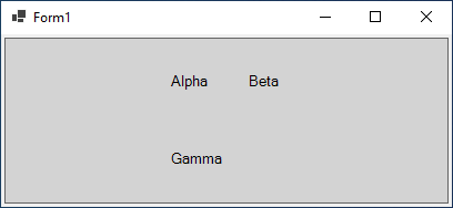
The diagram displays the three nodes that are in the model. Some interaction is already possible:
- Click and drag the background in the above diagram to pan the view.
- Click a node to select it, or press down on and drag a node to move it around.
- To create a selection box, click and hold on the background, then start dragging.
- Use Ctrl-C and Ctrl-V, or control-drag-and-drop, to make a copy of the selection.
- Press the Delete key to delete selected nodes. (Read about more Keyboard Commands.)
- On touch devices, press and hold to bring up a context menu. (Read about Context Menus.)
- Since the undo manager was enabled, Ctrl-Z and Ctrl-Y will undo and redo moves and copies and deletions.
Styling Nodes
Nodes are styled by creating templates consisting of GraphObjects and setting properties on those objects. To create a Node, we have several building block classes at our disposal:
- Shape, to display pre-defined or custom geometry with colors
- TextBlock, to display (potentially editable) text in various fonts
- Picture, to display images, including SVG files
- Panel, containers to hold a collection of other objects that can be positioned and sized in different manners according to the type of the Panel (like tables, vertical stacks, and stretching containers)
All of these building blocks are derived from the GraphObject abstract class, so we casually refer to them as GraphObjects or elements.
We want the model data properties to affect our Nodes, and this is done by way of data bindings. Data bindings allow us to change the appearance and behavior of GraphObjects in Nodes by automatically setting properties on those GraphObjects to values that are taken from the model data. The model data objects are C# objects. You can choose to use whatever property names you like on the node data in the model.
The default Node template is simple: A Node which contains one TextBlock.
There is a data binding between a TextBlock's Text property and
the model data's Key property. In code, the template looks
something like this:
  myDiagram.NodeTemplate =
    new Node()
      .Add(
        new TextBlock()
          // TextBlock.Text is bound to Node.Data.Key
          .Bind("Text", "Key"));
TextBlocks, Shapes, and Pictures are the primitive building blocks of GoDiagram. TextBlocks cannot contain images; Shapes cannot contain text. If you want your node to show some text, you must use a TextBlock. If you want to draw or fill some geometrical figures, you must use a Shape.
More generally, the skeleton of a Node template will look something like this:
  myDiagram.NodeTemplate =
    new Node("Vertical")  // argument of a Node (or any Panel) can be a Panel type
      /* set Node properties here */
      { LocationSpot = Spot.Center }

      /* add Bindings here */
      // example Node binding sets Node.Location to the value of Node.Data.Loc
      .Bind("Location", "Loc")

      /* add GraphObjects contained within the Node */
      .Add(
        // this Shape will be vertically above the TextBlock
        new Shape("RoundedRectangle")  // string argument can name a predefined figure
          { /* set Shape properties here */ }
          // example Shape binding sets Shape.Figure to the value of Node.Data.Fig
          .Bind("Figure", "Fig"),
        new TextBlock("default text")  // string argument can be initial text string
          { /* set TextBlock properties here */ }
          // example TextBlock binding sets TextBlock.Text to the value of Node.Data.Text
          .Bind("Text")
      );
The nesting of GraphObjects within Panels can be arbitrarily deep, and every class has its own unique set of properties to utilize, but this shows the general idea.
Now that we have seen how to make a Node template, let's see an example. We will make a simple template commonly seen in organizational diagrams — an image next to a name. Consider the following Node template:
-
A Node of "Horizontal" Panel type, meaning that its elements will be laid
out horizontally side-by-side. It has two elements:
- A Picture for the portrait, with the image source data bound
- A TextBlock for the name, with the text data bound
  private void Setup() {
    // enable Ctrl-Z to undo and Ctrl-Y to redo
    myDiagram.UndoManager.IsEnabled = true;

    // define a simple Node template
    myDiagram.NodeTemplate =
      new Node("Horizontal")
        // the entire node will have a light-blue background
        { Background = "#44CCFF" }
        .Add(
          new Picture
            // Pictures should normally have an explicit width and height.
            // This picture has a red background, only visible when there is no source set
            // or when the image is partially transparent.
            { Margin = 10, Width = 50, Height = 50, Background = "red" }
            // Picture.Source is data bound to the "Source" attribute of the model data
            .Bind("Source"),
          new TextBlock("Default Text")  // the initial value for TextBlock.Text
            // some room around the text, a larger font, and a white stroke:
            { Margin = 12, Stroke = "white", Font = new Font("Segoe UI", 16, FontWeight.Bold) }
            // TextBlock.Text is data bound to the "Name" property of the model data
            .Bind("Text", "Name")
        );

    myDiagram.Model = new MyModel {
      NodeDataSource = new List<NodeData> {
        new NodeData { Name = "Don Meow", Source = "cat1.png" },
        new NodeData { Name = "Copricat", Source = "cat2.png" },
        new NodeData { Name = "Demeter", Source = "cat3.png" },
        new NodeData()  // empty node data
      }
    };
  }

  ...

  // define the model
  public class MyModel : Model<NodeData, string, object> { }

  // note that each node data object holds whatever properties it needs;
  // for this app we add the "Name" and "Source" properties
  public class NodeData : MyModel.NodeData {
    public string Name { get; set; }
    public string Source { get; set; }
  }
That code produces this diagram:
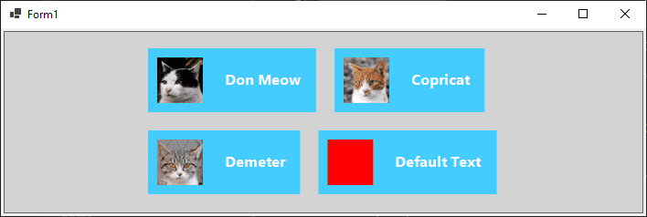
We may want to show some "default" state when not all information is present, for instance when an image does not load or when a name is not known. The "empty" node data in this example is used to show that node templates can work perfectly well without any of the properties on the bound data.
Kinds of Models
With a custom node template our diagram is becoming a pretty sight, but perhaps we want to show more. Perhaps we want an organizational chart to show that Don Meow is really the boss of a cat cartel. So we will create a complete organization chart diagram by adding some Links to show the relationship between individual nodes and a Layout to automatically position the nodes.
In order to get links into our diagram, the basic Model is not
going to cut it. We are going to have to pick one of the other two models in
GoDiagram, both of which support Links. These are
GraphLinksModel and TreeModel. (Read more about
models here.)
In GraphLinksModel, we have a Model.LinkDataSource in addition to
the Model.NodeDataSource. It holds an array of objects,
each describing a link by specifying the "To" and "From" node keys. Here's an
example where node A links to node B and where node B links to node C:
  myDiagram.Model = new MyModel {
    NodeDataSource = new List<NodeData> {
      new NodeData { Key = "A" },
      new NodeData { Key = "B" },
      new NodeData { Key = "C" }
    },
    LinkDataSource = new List<LinkData> {
      new LinkData { From = "A", To = "B" },
      new LinkData { From = "B", To = "C" }
    }
  };

  ...

  public class MyModel : GraphLinksModel<NodeData, string, object, LinkData, string, string> { }
  public class NodeData : MyModel.NodeData { }
  public class LinkData : MyModel.LinkData { }
A GraphLinksModel allows you to have any number of links between nodes, going in any direction. There could be ten links running from A to B, and three more running the opposite way, from B to A.
A TreeModel works a little differently. Instead of maintaining a separate collection of link data, the links in a tree model are created by specifying a "Parent" for a node data. Links are then created from this association. Here's the same example done as a TreeModel, with node A linking to node B and node B linking to node C:
  myDiagram.Model = new MyModel {
    NodeDataSource = new List<NodeData> {
      new NodeData { Key = "A" },
      new NodeData { Key = "B", Parent = "A" },
      new NodeData { Key = "C", Parent = "B" }
    }
  };

  ...

  public class MyModel : TreeModel<NodeData, string, object> { }
  public class NodeData : MyModel.NodeData { }
TreeModel is simpler than GraphLinksModel, but it cannot make arbitrary link relationships, such as multiple links between the same two nodes, or having multiple parents. Our organizational diagram is a simple hierarchical tree-like structure, so we will choose TreeModel for this example.
First, we will complete the data by adding a few more nodes, using a TreeModel, and specifying keys and parents in the data.
  private void Setup() {
    // enable Ctrl-Z to undo and Ctrl-Y to redo
    myDiagram.UndoManager.IsEnabled = true;

    // the template we defined earlier
    myDiagram.NodeTemplate =
      new Node("Horizontal")
        { Background = "#44CCFF" }
        .Add(
          new Picture
            { Margin = 10, Width = 50, Height = 50, Background = "red" }
            .Bind("Source"),
          new TextBlock("Default Text")
            { Margin = 12, Stroke = "white", Font = new Font("Segoe UI", 16, FontWeight.Bold) }
            .Bind("Text", "Name")
        );

    myDiagram.Model = new MyModel {
      NodeDataSource = new List<NodeData> {
        new NodeData { Key = "1",               Name = "Don Meow",   Source = "cat1.png" },
        new NodeData { Key = "2", Parent = "1", Name = "Demeter",    Source = "cat2.png" },
        new NodeData { Key = "3", Parent = "1", Name = "Copricat",   Source = "cat3.png" },
        new NodeData { Key = "4", Parent = "3", Name = "Jellylorum", Source = "cat4.png" },
        new NodeData { Key = "5", Parent = "3", Name = "Alonzo",     Source = "cat5.png" },
        new NodeData { Key = "6", Parent = "2", Name = "Munkustrap", Source = "cat6.png" }
      }
    };
  }

  ...

  // define the model
  public class MyModel : TreeModel<NodeData, string, object> { }

  // note that "Key" and "Parent" are included in the predefined TreeModel.NodeData;
  // for this app we add the "Name" and "Source" properties
  public class NodeData : MyModel.NodeData {
    public string Name { get; set; }
    public string Source { get; set; }
  }
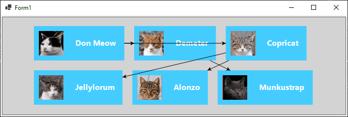
Diagram Layouts
As you can see the TreeModel automatically creates the necessary Links to associate the Nodes, but it's hard to tell whose parent is whom.
Diagrams have a default layout which takes all nodes that do not have a location and gives them locations, arranging them in a grid. We could explicitly give each of our nodes a location to sort out this organizational mess, but as an easier solution in our case, we will use a layout that gives us good locations automatically.
We want to show a hierarchy, and are already using a TreeModel, so the most
natural layout choice is TreeLayout. TreeLayout defaults to flowing from left
to right, so to get it to flow from top to bottom (as is common in
organizational diagrams), we will set the Angle property to 90.
Using layouts in GoDiagram is usually simple. Each kind of layout has a number of properties that affect the results. There are samples for each layout (like TreeLayout Demo) that showcase its properties.
  // define a TreeLayout that flows from top to bottom
  myDiagram.Layout = new TreeLayout { Angle = 90, LayerSpacing = 35 };
GoDiagram has many other layouts, which you can read about here.
Adding the layout to the diagram and model so far, we can see our results:
  private void Setup() {
    // enable Ctrl-Z to undo and Ctrl-Y to redo
    myDiagram.UndoManager.IsEnabled = true;
    // specify a Diagram.Layout that arranges trees
    myDiagram.Layout = new TreeLayout { Angle = 90, LayerSpacing = 35 };

    // the template we defined earlier
    myDiagram.NodeTemplate =
      new Node("Horizontal")
        { Background = "#44CCFF" }
        .Add(
          new Picture
            { Margin = 10, Width = 50, Height = 50, Background = "red" }
            .Bind("Source"),
          new TextBlock("Default Text")
            { Margin = 12, Stroke = "white", Font = new Font("Segoe UI", 16, FontWeight.Bold) }
            .Bind("Text", "Name")
        );

    // the same model as before
    myDiagram.Model = new MyModel {
      NodeDataSource = new List<NodeData> {
        new NodeData { Key = "1",               Name = "Don Meow",   Source = "cat1.png" },
        new NodeData { Key = "2", Parent = "1", Name = "Demeter",    Source = "cat2.png" },
        new NodeData { Key = "3", Parent = "1", Name = "Copricat",   Source = "cat3.png" },
        new NodeData { Key = "4", Parent = "3", Name = "Jellylorum", Source = "cat4.png" },
        new NodeData { Key = "5", Parent = "3", Name = "Alonzo",     Source = "cat5.png" },
        new NodeData { Key = "6", Parent = "2", Name = "Munkustrap", Source = "cat6.png" }
      }
    };
  }
Our diagram is starting to look like a proper organization chart, but we could do better with the links.
Link Templates
We will construct a new Link template that will better suit our wide, boxy
nodes. A Link is a different kind of Part,
not like a Node. The main element of a Link is the Link's shape, and must be a
Shape that will have its geometry computed dynamically by GoDiagram. Our
link is going to consist of just this shape, with its stroke a little thicker
than normal and dark gray instead of black. Unlike the default link template
we will not have an arrowhead. And we will change the Link
Routing property from Normal to Orthogonal, and give it a
Corner value so that right-angle turns are rounded.
  // define a Link template that routes orthogonally, with no arrowhead
  myDiagram.LinkTemplate =
    new Link
      // default routing is LinkRouting.Normal
      // default corner is 0
      { Routing = LinkRouting.Orthogonal, Corner = 5 }
      .Add(
        // the link path, a Shape
        new Shape { StrokeWidth = 3, Stroke = "#555" }
        // if we wanted an arrowhead we would also add another Shape with ToArrow defined:
        // new Shape { ToArrow = "Standard", Stroke = null }
      );
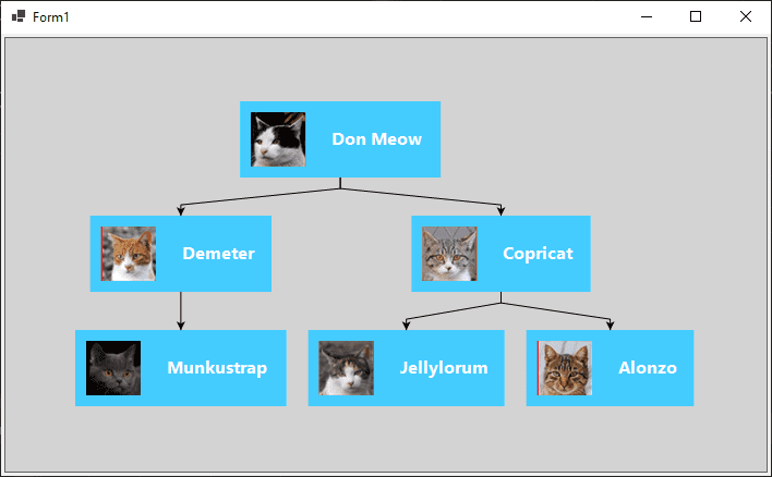
Combining our Link template with our Node template, TreeModel, and TreeLayout, we finally have a full organization diagram. The complete code is repeated below, and the resulting diagram follows:
  // Form1.cs
  using System.Collections.Generic;
  using Northwoods.Go;
  using Northwoods.Go.Layouts;
  using Northwoods.Go.Models;

  namespace WinFormsApp {
    public partial class Form1 : System.Windows.Forms.Form {
      private Diagram myDiagram;

      public Form1() {
        InitializeComponent();
        myDiagram = diagramControl1.Diagram;

        Setup();
      }

      private void Setup() {
        myDiagram.UndoManager.IsEnabled = true;
        myDiagram.Layout = new TreeLayout { Angle = 90, LayerSpacing = 35 };

        myDiagram.NodeTemplate =
          new Node("Horizontal")
            { Background = "#44CCFF" }
            .Add(
              new Picture
                { Margin = 10, Width = 50, Height = 50, Background = "red" }
                .Bind("Source"),
              new TextBlock("Default Text")
                { Margin = 12, Stroke = "white", Font = new Font("Segoe UI", 16, FontWeight.Bold) }
                .Bind("Text", "Name")
            );

        // define a Link template that routes orthogonally, with no arrowhead
        myDiagram.LinkTemplate =
          new Link
            { Routing = LinkRouting.Orthogonal, Corner = 5 }
            .Add(
              // the link's path shape
              new Shape { StrokeWidth = 3, Stroke = "#555" }
            );

        // it's best to declare all templates before assigning the model
        myDiagram.Model = new MyModel {
          NodeDataSource = new List<NodeData> {
            new NodeData { Key = "1",               Name = "Don Meow",   Source = "cat1.png" },
            new NodeData { Key = "2", Parent = "1", Name = "Demeter",    Source = "cat2.png" },
            new NodeData { Key = "3", Parent = "1", Name = "Copricat",   Source = "cat3.png" },
            new NodeData { Key = "4", Parent = "3", Name = "Jellylorum", Source = "cat4.png" },
            new NodeData { Key = "5", Parent = "3", Name = "Alonzo",     Source = "cat5.png" },
            new NodeData { Key = "6", Parent = "2", Name = "Munkustrap", Source = "cat6.png" }
          }
        };
      }
    }

    // define the model data
    public class MyModel : TreeModel<NodeData, string, object> { }
    public class NodeData : MyModel.NodeData {
      public string Name { get; set; }
      public string Source { get; set; }
    }
  }

Learn More
You may want to read more tutorials, such as the GraphObject Manipulation tutorial and the Interactivity tutorial.
Also consider looking at the samples to see some of the diagrams possible with GoDiagram, or read the technical introduction to get an in-depth look at the components of GoDiagram.