Geometry Path Strings
The GoDiagram Geometry class controls the "shape" of a Shape, whereas the Shape.Fill and Shape.Stroke and other shape properties control the colors and appearance of the shape. For common shape figures, there are predefined geometries that can be used by setting Shape.Figure. However one can also define custom geometries.
One can construct any Geometry by allocating and initializing a Geometry of at least one PathFigure holding some PathSegments. But you may find that using the string representation of a Geometry is easier to write and save in a database. Use the static method Geometry.Parse or the Shape.GeometryString property to transform a geometry path string into a Geometry object.
See samples that make use of Geometries in the samples index.
Geometry Path String Syntax
The syntax for a geometry path string is an extension of the SVG path string syntax. The string consists of a number of commands, each a single letter followed by some command-specific numeric parameters.
Below are the possible commands along with the parameters they take. The parameter notation (x y)+ means that the command requires exactly two
parameters, but there can be 1 or more sets of parameters for each command. For instance, the L (x y)+ command can be written as
L 10 10 20 20 to denote two straight line segments.
Commands written with an uppercase letter indicate absolute coordinates; lowercase commands specify coordinates relative to the last command. Some commands do not care about case because they do not take coordinates as arguments.
-
Move commands begin a new subpath in a PathFigure. One is essential to begin a PathFigure and therefore must be the first segment type in the path string, with the exception of a Fill command (M (x y)+F) that can precede it.Additional sets of parameters for a move command are automatically considered Line commands, so
M 10 10 20 20is identical toM 10 10 L 20 20. -
Line command adds a straight line segment from the previous point to the new point.L (x y)+ -
Horizontal line command specifies only an x value for a straight horizontal line.H (x)+ -
Vertical line command specifies only a y value for a straight vertical line.V (y)+ -
Quadratic Bezier Curves.Q (x1 y1 x y)+x1,y1is the control point. See SVG Quadratic Bezier command for more details. -
Short-hand Quadratic Bezier Curves. The control point is calculated based on SVG's path rules.T (x y)+ -
Cubic Bezier Curves.C (x1 y1 x2 y2 x y)+x1,y1andx2,y2are the control points. See SVG Cubic Bezier command for more details. -
Short-hand Cubic Bezier Curves. The two control points are calculated based on SVG's path rules.S (x2 y2 x y)+ -
Elliptical Arcs. These follow the SVG arc conventions.A (rx ry x-axis-rotation large-arc-flag sweep-flag x y)+ -
ZZdenotes that the current segment is closed. This is placed after the last segment of a subpath. There are no parameters, and case does not matter with this command.
For detailed information on the SVG path strings, see the W3C's page on SVG Paths.
Additionally there are some tokens specific to GoDiagram:
-
Arcs following GoDiagram canvas arc convention. These arcs create a new line from the last point in the subpath to the first point of an arc defined by the five arguments. Unlike all other commands with parameters, multiple sets of parameters are not allowed for B-arcs.B (startAngle, sweepAngle, centerX, centerY, radiusX, radiusY) -
Used beforeXMcommands to denote separate PathFigures instead of a subpath. There are no parameters, and case does not matter with this command. Separate PathFigures are important when different fills are desired per figure component. -
The existence of this command specifies whether the current PathFigure is filled (true ifFFis present). This is placed at the beginning of a figure. There is an optional parameter that is currently ignored. Case does not matter with this command. -
The existence of this command specifies whether the current PathFigure is shadowed (false ifUUis present. A shadowed PathFigure is the default). Shadows on shapes (and therefore PathFigures) only exist if Part.IsShadowed is set to true on the containing part. This is placed at the beginning of a figure. Case does not matter with this command.
Geometry Path String Examples
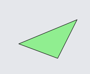
Here is a simple usage of a geometry path string when initializing a Shape without setting Shape.Figure:
  diagram.Add(
    new Node()
      .Add(
        new Shape {
          GeometryString = "F M120 0 L80 80 0 50z",
          Fill = "lightgreen"
        }
      )
  );
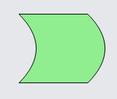
Here is a geometry path string that uses quadratic Bezier curves:
  diagram.Add(
    new Node()
      .Add(
        new Shape {
          GeometryString = "F M0 0 L100 0 Q150 50 100 100 L0 100 Q50 50 0 0z",
          Fill = "lightgreen"
        }
      )
  );
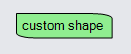
This geometry uses GoDiagram arcs:
  diagram.Add(
    new Node("Spot")
      .Add(
        new Shape {
          GeometryString = "F M0 0 L80 0 B-90 90 80 20 20 20 L100 100 20 100 B90 90 20 80 20 20z",
          Fill = "lightgreen"
        },
        new TextBlock("custom shape")
      )
  );
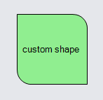
The following geometry uses GoDiagram arcs. Because the Shape is stretched to fit around the TextBlock, and because the default value of Shape.GeometryStretch causes the Geometry to be stretched too, the custom geometry is also stretched to fit around the text.
  diagram.Add(
    new Node("Auto")
      .Add(
        new Shape {
          GeometryString = "F M0 0 L.8 0 B-90 90 .8 .2 .2 .2 L1 1 .2 1 B90 90 .2 .8 .2 .2z",
          Fill = "lightgreen"
        },
        new TextBlock("custom shape") { Margin = 4 }
      )
  );
In the following Diagram we use a path string that contains three PathFigures. Note the X commands separating the figures and the
F commands denoting fill.
  diagram.Add(
    new Part()
      .Add(
        new Shape {
          GeometryString =
            "F M 0 0 l 30,30 10,10 35,0 0,-35 x m 50 0 l 0,-50 10,0 35,35 x" +
            "f m 50 0 l 0,-50 10,0 35,35z",
          StrokeWidth = 10, Stroke = "lightblue", Fill = "gray"
        }
      )
  );
 The first two PathFigures are open; the first and third figures are filled. The
 Z command only closes the PathFigure that it ends.
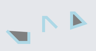
In the following Diagram we use a path string that contains four PathFigures, two of which have a shadow. Note that figures are shadowed by default if the
containing Part has Part.IsShadowed set to true. To un-shadow specific path figures we use the U command.
  diagram.Add(
    new Part { IsShadowed = true, ShadowBlur = 0, ShadowOffset = new Point(10, 10) }
      .Add(
        new Shape {
          GeometryString =
            "F M 0 0 l 30,30 10,10 35,0 0,-35 x u m 50 0 l 0,-50 10,0 35,35 x" +
            "u f m 50 0 l 0,-50 10,0 35,35z x m 70 0 l 0,30 30,0 5,-35z",
          StrokeWidth = 8, Stroke = "lightblue", Fill = "lightcoral"
        }
      )
  );
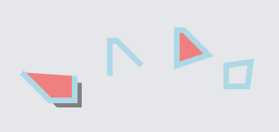 The first and last PathFigures are shadowed; the second and third are unshadowed. Note that in WinForms, the last is not shadowed because it has no fill.
Geometry.Parse
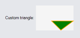
Use the static method Geometry.Parse to convert a GoDiagram syntax path string into a Geometry.
  diagram.Add(
    new Node("Horizontal")
      .Add(
        new TextBlock("Custom triangle:"),
        new Shape {
          Geometry = Geometry.Parse("M120 0 L80 80 0 50z"), // Geometry is not filled
          Fill = "green", Background = "whitesmoke",
          Stroke = "orange", StrokeWidth = 2
        }
      )
  );
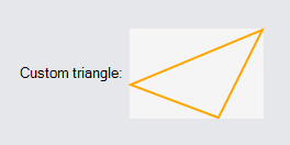
Note that even though a Shape.Fill is specified, the shape does not appear filled. This is because the geometry's one PathFigure is not declared
to be filled -- there is no F command. Importing SVG path strings that are filled also requires declaring that the geometry is filled. There are
several ways to do that:
- Call Geometry.FillPath for converting the SVG path string to GoDiagram syntax before calling Geometry.Parse. For literal SVG path strings it is often easiest just to prefix it with "F ".
- Call Geometry.Parse with a second argument that is true.
- Modify the Geometry returned by Geometry.Parse, by setting PathFigure.IsFilled to true on the desired PathFigures.
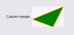
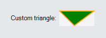
Here is the same example, but using a filled geometry path string.
  diagram.Add(
    new Node("Horizontal")
      .Add(
        new TextBlock("Custom triangle:"),
        new Shape {
          Geometry = Geometry.Parse("F M120 0 L80 80 0 50z"), // Geometry is filled
          Fill = "green", Background = "whitesmoke",
          Stroke = "orange", StrokeWidth = 2
        }
      )
  );
All Geometry objects have bounds that contain the origin, so a geometry created with no points at x==0 or y==0 will have extra space to the left of it or above it. Note how there is extra space in the following node, causing the shape to appear farther away from the text and shifted down:
  diagram.Add(
    new Node("Horizontal")
      .Add(
        new TextBlock("Custom triangle:"),
        new Shape {
          Geometry = Geometry.Parse("M120 50 L80 80 50 50z", true), // Geometry is filled
          Fill = "green", Background = "whitesmoke",
          Stroke = "orange", StrokeWidth = 2
        }
      )
  );
Often when importing SVG shapes created by drawing applications into GoDiagram we do not want any extra space above or to the left, so we need to normalize the geometry. There is a function for this, Geometry.Normalize, which modifies the Geometry's points in-place and returns a Point describing the amount they were offset.
  var geo = Geometry.Parse("M120 50 L80 80 50 50z", true);
  geo.Normalize();

  diagram.Add(
    new Node("Horizontal")
      .Add(
        new TextBlock("Custom triangle:"),
        new Shape {
          Geometry = geo, // normalized above
          Fill = "green", Background = "whitesmoke",
          Stroke = "orange", StrokeWidth = 2
        }
      )
  );
Shape.GeometryString
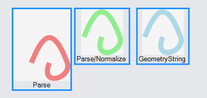
The Shape.GeometryString property setter parses a given GoDiagram path string as a Geometry, normalizes it, sets the Shape.Geometry to this new Geometry, and offsets the Shape's position by the amount it was shifted in normalization. The positioning is useful when the shape is inside a PanelLayoutPosition panel. But when the shape is used in any other kind of panel (thus ignoring the GraphObject.Position), it is still useful to remove the extra space so that the shape fits in well with the other objects in the panel.
The example below adds three Parts with Shapes to the diagram. The first shape uses Geometry.Parse to set the Shape's Geometry, the second one uses Geometry.Parse and Geometry.Normalize. The third uses Shape.GeometryString. Note the difference in size between the first Part and the other two.
  var pathstring = "M30 100 C 50 50, 70 20, 100 100, 110, 130, 45, 150, 65, 100";

  // Just parsing the geometry
  diagram.Add(
    new Node("Vertical")
      .Add(
        new Shape {
          Geometry = Geometry.Parse(pathstring),
          StrokeWidth = 10, Stroke = "lightcoral",
          Background = "whitesmoke"
        },
        new TextBlock("Parse")
      )
  );

  // Parsing the geometry and normalizing it
  var geo = Geometry.Parse(pathstring);
  geo.Normalize();
  diagram.Add(
    new Node("Vertical")
      .Add(
        new Shape {
          Geometry = geo,
          StrokeWidth = 10, Stroke = "lightgreen",
          Background = "whitesmoke"
        },
        new TextBlock("Parse/Normalize")
      )
  );

  // Using GeometryString to parse and normalize the geometry
  diagram.Add(
    new Node("Vertical")
      .Add(
        new Shape {
          GeometryString = pathstring,
          StrokeWidth = 10, Stroke = "lightblue",
          Background = "whitesmoke"
        },
        new TextBlock("GeometryString")
      )
  );

  diagram.Layout = new GridLayout();

  // Select them all to more easily see their sizes
  diagram.CommandHandler.SelectAll();
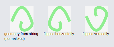
Flipping Geometries Horizontally and Vertically
GoDiagram Geometries have several methods for modifying the geometry's points by a transformation matrix. We can use these methods to flip or mirror the geometries if needed.
geometry.Scale(-1, 1) will flip a geometry horizontally. geometry.Scale(1, -1) will flip a geometry vertically.
  var pathstring = "M30 100 C 50 50, 70 20, 100 100, 110, 130, 45, 150, 65, 100";
  var geo = Geometry.Parse(pathstring);
  geo.Normalize();

  diagram.Add(
    new Node("Vertical")
      .Add(
        new Shape {
          Geometry = geo,
          StrokeWidth = 10, Stroke = "lightgreen",
          Background = "whitesmoke"
        },
        new TextBlock("geometry from string\n(normalized)")
      )
  );

  var geo2 = geo.Copy();
  geo2.Scale(-1, 1);  // flips a geometry horizontally
  diagram.Add(
    new Node("Vertical")
      .Add(
        new Shape {
          Geometry = geo2,
          StrokeWidth = 10, Stroke = "lightgreen",
          Background = "whitesmoke"
        },
        new TextBlock("flipped horizontally")
      )
  );

  var geo3 = geo.Copy();
  geo3.Scale(1, -1);  // flips a geometry vertically
  diagram.Add(
    new Node("Vertical")
      .Add(
        new Shape {
          Geometry = geo3,
          StrokeWidth = 10, Stroke = "lightgreen",
          Background = "whitesmoke"
        },
        new TextBlock("flipped vertically")
      )
  );

  diagram.Layout = new GridLayout();
Converting Path Strings
The static method Geometry.Stringify can be used to output a Geometry as a string. This string will have the GoDiagram path string syntax. You can use Geometry.Stringify and Geometry.Parse to data bind custom shape geometries.
Geometry.Parse(Geometry.Stringify(myGeometry)) will return a geometry equal to myGeometry, though if myGeometry was created from a
string, the string itself is not guaranteed to be the same. If you merely want to copy a Geometry you should use Geometry.Copy.
// These path strings represent identical geometries:
var a = "m0 0 t 50 50, q 40 20, 50 10 h 10 v -23 l 45, 5, 65, 100";
var b = "M0 0 Q0 0 50 50 Q90 70 100 60 L110 60 L110 37 L155 42 L220 142";
Geometry.Stringify(Geometry.Parse(a)); // returns the string in a
Geometry.Stringify(Geometry.Parse(b)); // returns the string in b
Because of the additional non-SVG commands, a string generated from Geometry.Stringify will not necessarily be a valid SVG path.
The static method Geometry.FillPath takes a path string of either syntax and adds F tokens before each PathFigure that does not have them.
Because SVG path strings are not considered to be "filled" by themselves, if you are converting an SVG Path shape to GoDiagram you will want to call
Geometry.FillPath on the SVG string.
Geometry.FillPath("M0 0 L20 20 L20 0");
// returns "F M0 0 L20 20 L20 0"
Parameterized Geometries
Although individual Geometry objects cannot be dynamically parameterized based on the intended size or other properties, the Shape class does support such parameterization via Shape.DefineFigureGenerator. When you set or bind the Shape.Figure property, the shape will call the named figure generator to generate a Geometry appropriate for the desired width and height and other Shape properties.
You can see the definitions of all of the predefined figures in the extensions file: Figures.cs.