Graduated Panels
The "Graduated" Panel, PanelLayoutGraduated, draws regular tick marks and/or text labels along the stroke of the main child Shape. Graduated Panels can be considered scales showing a range of values.
For examples of Graduated Panels see the Timeline, Thermometer, Instrument Gauge, and Rulered Diagram samples.
Simple Graduated Panels
Similar to Auto and Spot Panels, Graduated Panels should have two or more elements in them. Elements must be either Shapes or TextBlocks. The main Shape element may be declared by setting GraphObject.IsPanelMain to true; but no such setting is needed if it is the very first element of the panel. Shapes and TextBlocks, other than the main Shape, basically act as templates for the drawing of each tick mark and label.
Tick mark Shapes within a Graduated Panel should have a measured size, either by setting a GraphObject.DesiredSize (or Width and
Height properties), or by setting its Shape.Geometry. For basic tick marks drawn normal to the main Shape's path, it is easiest to use a
simple vertical line geometry string: M0 0 V10. The height of the geometry will determine the length of the tick mark.
diagram.Add(
new Part("Graduated")
.Add(
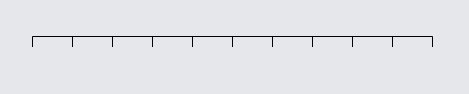
new Shape { GeometryString = "M0 0 H400" }, // the main shape, a horizontal line
new Shape { GeometryString = "M0 0 V10" } // a tick mark, a vertical line
)
);
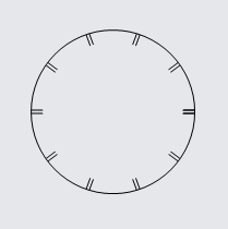
Any shape, including custom geometries, can be used as the main Shape or as a tick mark Shape of a Graduated Panel.
  diagram.Add(
    new Part("Graduated") { Background = "transparent" }  // make panel pickable
      .Add(
        // main shape is a whole circle
        new Shape("Circle") { Fill = null, DesiredSize = new Size(150, 150) },
        // tick shape is a double line
        new Shape { GeometryString = "M0 0 V10 M3 0 V10" }
      )
  );
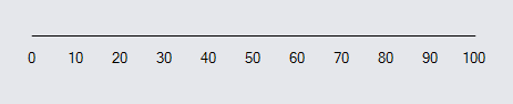
Graduated Panels can also be labeled with TextBlocks denoting the values along the scale. Often, these will be offset from the main stroke using GraphObject.SegmentOffset, as one would with Link labels, so that the text does not overlap the main stroke. More detail on placing labels is in the "Appearance" section below.
  diagram.Add(
    new Part("Graduated") { Background = "transparent" }  // make panel pickable
      .Add(
        new Shape { GeometryString = "M0 0 H400" },  // the main shape
        new TextBlock { SegmentOffset = new Point(0, 12) }  // tick labels
      )
  );
Graduated Panel Properties
There are a number of properties that govern the appearance of tick marks and labels.
Tick Mark Values
The graduated values of a Graduated Panel will range on a linear scale from the start of the main shape's stroke to the end of the stroke. The values and frequency of tick marks and labels are governed by a few properties:
- Panel.GraduatedMin - the minimum value represented on the scale, at the beginning of the stroke of the main shape
- Panel.GraduatedMax - the maximum value represented on the scale, at the end of the main shape
- Panel.GraduatedTickBase - the value of the "origin" tick mark, the first tick mark if it is the same as GraduatedMin
- Panel.GraduatedTickUnit - tick marks are positioned at multiples of the GraduatedTickUnit added to the GraduatedTickBase
- Shape.Interval/TextBlock.Interval - a multiple of the GraduatedTickUnit at which to draw a tick or label
Graduated Panels can have multiple Shapes as tick marks and multiple TextBlocks as labels, with the interval property controlling at what multiples of the
GraduatedTickUnit they are drawn. In many of the examples below, larger ticks are drawn at intervals of 4; some have an interval of 5.
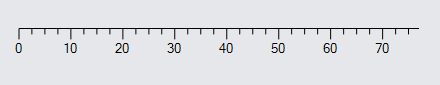
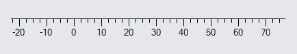
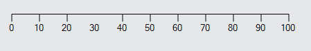
A GraduatedMin of 0, GraduatedMax of 77, GraduatedTickBase of 0,
GraduatedTickUnit of 2.5, and intervals of 4 result in a scale that might appear as:
  diagram.Add(
    new Part("Graduated") {
        GraduatedMin = 0, GraduatedMax = 77,
        GraduatedTickBase = 0, GraduatedTickUnit = 2.5,
        Background = "transparent"
      }
      .Add(
        new Shape { GeometryString = "M0 0 H400" },  // the main shape
        // a short, frequent tick mark
        new Shape { GeometryString = "M0 0 V5" },
        // a longer tick mark every four ticks
        new Shape { GeometryString = "M0 0 V10", Interval = 4 },
        // text label only every four ticks, with a vertical offset
        new TextBlock { SegmentOffset = new Point(0, 12), Interval = 4 }
      )
  );
Changing GraduatedMin to -23 results in:
  diagram.Add(
    new Part("Graduated") {
        GraduatedMin = -23, GraduatedMax = 77,
        GraduatedTickBase = 0, GraduatedTickUnit = 2.5,
        Background = "transparent"
      }
      .Add(
        new Shape { GeometryString = "M0 0 H400" },  // the main shape
        new Shape { GeometryString = "M0 0 V5" }, // short tick mark
        new Shape { GeometryString = "M0 0 V10", Interval = 4 },  // long tick mark
        new TextBlock { SegmentOffset = new Point(0, 12), Interval = 4 }  // labels
      )
  );
The range from the min to the max value (Panel.GraduatedRange) has increased from 77 to 100, so the tick marks are closer to each other for the same length main path.
Changing GraduatedTickBase to 1.2 results in:
  diagram.Add(
    new Part("Graduated") {
        GraduatedMin = -23, GraduatedMax = 77,
        GraduatedTickBase = 1.2, GraduatedTickUnit = 2.5,
        Background = "transparent"
      }
      .Add(
        new Shape { GeometryString = "M0 0 H400" },  // the main shape
        new Shape { GeometryString = "M0 0 V5" }, // short tick mark
        new Shape { GeometryString = "M0 0 V10", Interval = 4 },  // long tick mark
        new TextBlock { SegmentOffset = new Point(0, 12), Interval = 4 }  // labels
      )
  );
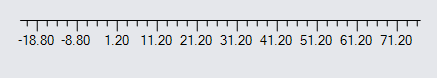
Basically, the "origin" for the scale has shifted slightly, even though the end values remain the same. There will always be a tick mark at the
GraduatedTickBase
if that value is within the range of the graduated scale.
Doubling the GraduatedTickUnit to 5 results in:
  diagram.Add(
    new Part("Graduated") {
        GraduatedMin = -23, GraduatedMax = 77,
        GraduatedTickBase = 1.2, GraduatedTickUnit = 5,
        Background = "transparent"
      }
      .Add(
        new Shape { GeometryString = "M0 0 H400" },  // the main shape
        new Shape { GeometryString = "M0 0 V5" }, // short tick mark
        new Shape { GeometryString = "M0 0 V10", Interval = 4 },  // long tick mark
        new TextBlock { SegmentOffset = new Point(0, 12), Interval = 4 }  // labels
      )
  );
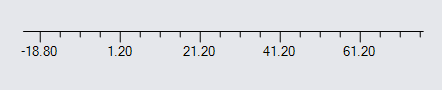
Doubling the tick unit halves the number of ticks for the same length path, but again the end values are unchanged.
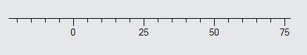
Changing GraduatedTickBase back to 0 and the intervals to 5 results in:
  diagram.Add(
    new Part("Graduated") {
        GraduatedMin = -23, GraduatedMax = 77,
        GraduatedTickBase = 0, GraduatedTickUnit = 5,
        Background = "transparent"
      }
      .Add(
        new Shape { GeometryString = "M0 0 H400" },  // the main shape
        new Shape { GeometryString = "M0 0 V5" }, // short tick mark
        new Shape { GeometryString = "M0 0 V10", Interval = 5 },  // long tick mark
        new TextBlock { SegmentOffset = new Point(0, 12), Interval = 5 }  // labels
      )
  );
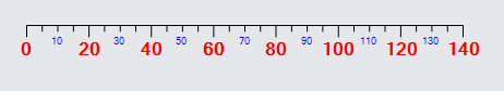
You can have more than one label. For example, small text that is more frequent than larger text:
  diagram.Add(
    new Part("Graduated") {
        GraduatedMin = 0, GraduatedMax = 140,
        GraduatedTickBase = 0, GraduatedTickUnit = 5,
        Background = "transparent"
      }
      .Add(
        new Shape { GeometryString = "M0 0 H400" },
        new Shape { GeometryString = "M0 0 V5" },
        new Shape { GeometryString = "M0 0 V10", Interval = 4 },
        // minor label
        new TextBlock {
            Interval = 2, SegmentOffset = new Point(0, 8),
            Stroke = "blue", Font = new Font("Segoe UI", 7, FontUnit.Point)
          },
        // major label
        new TextBlock {
          Interval = 4, SegmentOffset = new Point(0, 12),
          Stroke = "red", Font = new Font("Segoe UI", 12, FontWeight.Bold, FontUnit.Point)
        }
      )
  );
Tick Mark Appearance
The appearance of tick marks relative to the main shape path is controlled by a few properties:
- GraphObject.AlignmentFocus - the spot on the tick or label to align with the calculated path points, defaulting to the top center
- GraphObject.SegmentOffset - how much to offset a TextBlock label from the main stroke -- the Y value specifies distance from the path
- GraphObject.SegmentOrientation - how to rotate a TextBlock label relative to the main stroke
Only TextBlock labels should set the GraphObject.SegmentOffset or GraphObject.SegmentOrientation. They have no impact on the main shape or tick shapes. These GraphObject properties are also commonly used to place Link labels, as seen in the Introduction page on Link labels, and are used by Graduated Panels in a similar manner.
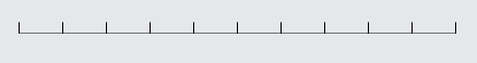
Setting AlignmentFocus to Spot.Bottom will cause the ticks to have their bottoms aligned to the main stroke:
  diagram.Add(
    new Part("Graduated")
      .Add(
        new Shape { GeometryString = "M0 0 H400" },
        new Shape { GeometryString = "M0 0 V10", AlignmentFocus = Spot.Bottom }
      )
  );
Setting AlignmentFocus to Spot.Center will cause the ticks to be centered across the path:
  diagram.Add(
    new Part("Graduated")
      .Add(
        new Shape { GeometryString = "M0 0 H400" },
        new Shape { GeometryString = "M0 0 V10 M0 20 V30", AlignmentFocus = Spot.Center }
      )
  );
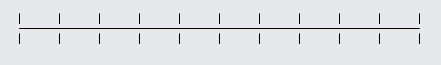
Note the gap in the geometry of the shape.
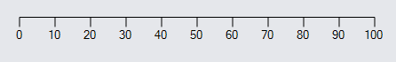
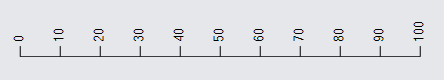
Setting SegmentOffset for labels can make them more readable near tick marks:
  diagram.Add(
    new Part("Graduated")
      .Add(
        new Shape { GeometryString = "M0 0 H400" },
        new Shape { GeometryString = "M0 0 V10" },
        // offset to display below ticks
        new TextBlock { SegmentOffset = new Point(0, 12) }
      )
  );
Setting SegmentOrientation for labels can alter the angle at which they are drawn relative to the main stroke:
  diagram.Add(
    new Part("Graduated")
      .Add(
        new Shape { GeometryString = "M0 0 H400" },
        new Shape { GeometryString = "M0 0 V10" },
        // change the angle of the text
        new TextBlock { SegmentOrientation = Orientation.Minus90 }
      )
  );
Note that the top-center point of each label is exactly at the point along the path for that value.
Combining these two properties and re-aligning the tick marks:
  diagram.Add(
    new Part("Graduated")
      .Add(
        new Shape { GeometryString = "M0 0 H400" },
        new Shape { GeometryString = "M0 0 V10", AlignmentFocus = Spot.Bottom },
        new TextBlock {
          AlignmentFocus = Spot.Left,
          SegmentOffset = new Point(0, -12),
          SegmentOrientation = Orientation.Minus90
        }
      )
  );
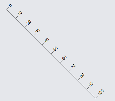
These properties behave similarly to Link labels, in that they respond to the direction of the main stroke. For example, let us turn the main shape so that it goes diagonally down from the top-left to the bottom-right.
  diagram.Add(
    new Part("Graduated")
      .Add(
        new Shape { GeometryString = "M0 0 L285 285" },
        new Shape { GeometryString = "M0 0 V10", AlignmentFocus = Spot.Bottom },
        new TextBlock {
          AlignmentFocus = Spot.Left,
          SegmentOffset = new Point(0, -12),
          SegmentOrientation = Orientation.Minus90
        }
      )
  );
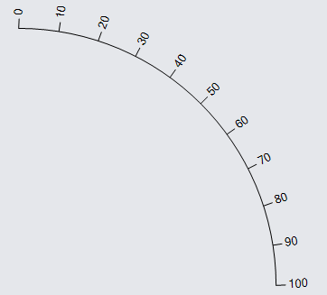
Now let us try a curve:
  diagram.Add(
    new Part("Graduated")
      .Add(
        new Shape("Curve1") { DesiredSize = new Size(285, 285) },
        new Shape { GeometryString = "M0 0 V10", AlignmentFocus = Spot.Bottom },
        new TextBlock {
          AlignmentFocus = Spot.Left,
          SegmentOffset = new Point(0, -12),
          SegmentOrientation = Orientation.Minus90
        }
      )
  );
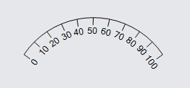
Here's another commonplace configuration:
  diagram.Add(
    new Part("Graduated")
      .Add(
        new Shape { GeometryString = "M0 0 A120 120 0 0 1 200 0" },  // an arc
        new Shape { GeometryString = "M0 0 V10" },
        new TextBlock {
          SegmentOffset = new Point(0, 12),
          SegmentOrientation = Orientation.Along
        }
      )
  );
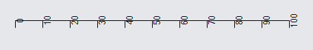
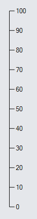
For vertical lines, it's not necessary to rotate the text:
  diagram.Add(
    new Part("Graduated")
      .Add(
        new Shape { GeometryString = "M0 0 V400" },
        new Shape { GeometryString = "M0 0 V10", AlignmentFocus = Spot.Bottom },
        new TextBlock {
          AlignmentFocus = Spot.Left,
          SegmentOffset = new Point(0, -12)
        }
      )
  );
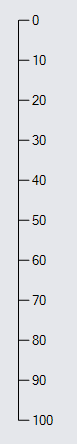
We can also go from bottom to top:
  diagram.Add(
    new Part("Graduated")
      .Add(
        new Shape { GeometryString = "M0 0 V-400" },
        new Shape { GeometryString = "M0 0 V10", AlignmentFocus = Spot.Top },
        new TextBlock {
          AlignmentFocus = Spot.Left,
          SegmentOffset = new Point(0, 12)
        }
      )
  );
Note how the Geometry goes from 0,0 to 0,-400, because negative Y values are higher on the screen/page. Note how because everything is relative to the path,
the tick marks and labels would be on the opposite side, so we have also changed the AlignmentFocus and SegmentOffset to have
opposite values from the previous example.
Lastly, any angle specified on a label will be respected if orientation is one of Orientation.None, Orientation.Along, or Orientation.Upright. In the case of Along and Upright, the angle will be added to the slope of the main path at the point of the TextBlock.
  diagram.Add(
    new Part("Spot")
      .Add(
        new Panel("Graduated")
          .Add(
            new Shape { GeometryString = "M0 0 L100 0 100 100 L0 100" },
            new Shape { GeometryString = "M0 0 V10" },
            new TextBlock {
              Interval = 5,
              Angle = 45,
              SegmentOffset = new Point(0, 12)
            }
          ),
        new TextBlock("None")
      )
  );

  diagram.Add(
    new Part("Spot")
      .Add(
        new Panel("Graduated")
          .Add(
            new Shape { GeometryString = "M0 0 L100 0 100 100 L0 100" },
            new Shape { GeometryString = "M0 0 V10" },
            new TextBlock {
              Interval = 5,
              Angle = 45,
              SegmentOrientation = Orientation.Along,
              SegmentOffset = new Point(0, 12)
            }
          ),
        new TextBlock("Along")
      )
  );

  diagram.Add(
    new Part("Spot")
      .Add(
        new Panel("Graduated")
          .Add(
            new Shape { GeometryString = "M0 0 L100 0 100 100 L0 100" },
            new Shape { GeometryString = "M0 0 V10" },
            new TextBlock {
              Interval = 5,
              Angle = 45,
              SegmentOrientation = Orientation.Upright,
              SegmentOffset = new Point(0, 12)
            }
          ),
        new TextBlock("Upright")
      )
  );
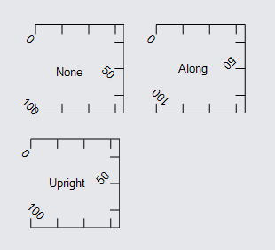
With None, the labels are always 45 degrees. With Along, the labels are always 45 degrees more than the slope. With Upright, the labels are always 45 degrees more than the slope, then rotated upright if necessary.
Functional Appearance Properties
There are also some functional properties allowing for further customization of the appearance of ticks and labels.
- Shape.GraduatedSkip/TextBlock.GraduatedSkip - an optional function which returns true for values that should be skipped while drawing a particular tick or label
- TextBlock.GraduatedFunction - an optional function which converts a value to a string to be displayed at that value -- if not defined, the default returns the value rounded to at most two decimals
Setting GraduatedSkip allows for skipping ticks where the supplied function returns true:
  diagram.Add(
    new Part("Graduated")
      .Add(
        new Shape { GeometryString = "M0 0 H400" },
        new Shape {
          // skip drawing tick at 30
          GraduatedSkip = v => v == 30,
          GeometryString = "M0 0 V10"
        },
        new TextBlock { SegmentOffset = new Point(0, 12) }
      )
  );
GraduatedSkip can also be used to draw ticks along only a portion of the main shape.
  diagram.Add(
    new Part("Graduated")
      .Add(
        new Shape { GeometryString = "M0 0 H400" },
        new Shape { GeometryString = "M0 0 V10", GraduatedSkip = v => v < 25 || v > 75 }
      )
  );
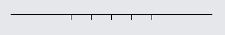
In this case, tick marks are now only drawn in the middle half of the main shape.
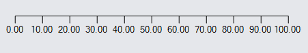
Setting GraduatedFunction allows for changing the way labels are displayed:
  diagram.Add(
    new Part("Graduated")
      .Add(
        new Shape { GeometryString = "M0 0 H400" },
        new Shape { GeometryString = "M0 0 V10" },
        new TextBlock {
          // always display two decimals
          GraduatedFunction = v => v.ToString("N2"),
          SegmentOffset = new Point(0, 12)
        }
      )
  );
Graduated Value Computations
There are some methods available for computing points along graduated paths:
- Panel.GraduatedPointForValue - returns the Point along the main shape at some value between GraduatedMin and GraduatedMax in Panel coordinates
- Panel.GraduatedValueForPoint - returns the value along the main shape nearest a given Point
In the following example, the red marker uses a Part.DragComputation function that keeps it along the path of the Graduated Panel using the above functions.
  var gauge =
    new Part("Auto") { Location = new Point(10, 20) }
      .Add(
        new Shape { Fill = "white" },
        new Panel("Graduated") { Name = "SCALE", Margin = 10 }
          .Add(
            new Shape { GeometryString = "M0 0 A120 120 0 0 1 200 0" },
            new Shape { GeometryString = "M0 0 V10" },
            new TextBlock { SegmentOffset = new Point(0, 12), SegmentOrientation = Orientation.Along }
          )
      );
  diagram.Add(gauge);

  var marker =
    new Part("Spot") {
        LocationSpot = Spot.Center, SelectionAdorned = false,
        DragComputation = (node, pt, _) => {
          var scale = gauge.FindElement("SCALE") as Panel;
          var loc = scale.GetLocalPoint(pt);
          var val = scale.GraduatedValueForPoint(loc);
          var gpt = scale.GraduatedPointForValue(val);
          return scale.GetDocumentPoint(gpt);
        }
      }
      .Add(
        new Shape("Circle") { Fill = "transparent", StrokeWidth = 0, Cursor = "pointer" },
        new Shape("Circle") { Fill = "red", StrokeWidth = 0, Width = 8, Height = 8 }
      );
  diagram.Add(marker);

  // once everything has been positioned, give the marker its location
  diagram.InitialLayoutCompleted += (s, e) => {
    var scale = gauge.FindElement("SCALE") as Panel;
    var gpt = scale.GraduatedPointForValue(0);
    marker.Location = scale.GetDocumentPoint(gpt);
  };
As you drag the red circle, you will notice that it always stays on the main shape's stroke. The computation converts the point to the panel's coordinate system, computes the closest graduated value, computes the point on the shape geometry for that value, and finally converts it back to document coordinates for use as the marker's location.
Note that for demonstration purposes this example has the marker being a separate Part from the "gauge" Part. A real gauge would have the marker be part of the gauge as an indicator of a particular value, optionally draggable by the user. See some examples at Instrument Controls: Gauges and Meters.
Other Considerations
By default, only the main shape of a Graduated Panel can be used to pick the panel. As with Grid Panels, a Graduated Panel should have a non-null
Background if the entire panel needs to be pickable. You cannot set or bind the Panel.ItemList of a Graduated Panel. You can set and bind
properties on tick Shapes and TextBlock labels as you can with any other GraphObject properties.
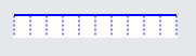
  diagram.Add(
    new Part("Graduated") { Background = "white" }
      .Add(
        new Shape { GeometryString = "M0 0 H150", Stroke = "blue", StrokeWidth = 2 },
        new Shape { GeometryString = "M0 0 V20", Stroke = "blue", StrokeDashArray = new float[] { 2, 2 } }
      )
  );
Events on the tick Shapes and TextBlock labels will be ignored. Rotating the main shape will not rotate the ticks, just as rotating a Spot Panel's main element won't rotate its children. Rotation should generally be done at the Panel level. Another similarity to Spot Panels is that resizing of a Graduated Panel should generally be done on the main shape. TextBlock labels cannot be edited.