Tools
Tools handle all of the input events. There are many kinds of predefined Tool classes that implement all of the common operations that users do.
For flexibility and simplicity, all input events are canonicalized as InputEvents and redirected by the diagram to go to the Diagram.CurrentTool. By default the Diagram.CurrentTool is an instance of ToolManager held as the Diagram.ToolManager. The ToolManager implements support for all mode-less tools. The ToolManager is responsible for finding another tool that is ready to run and then making it the new current tool. This causes the new tool to process all of the input events (mouse, keyboard, and touch) until the tool decides that it is finished, at which time the diagram's current tool reverts back to the Diagram.DefaultTool, which is normally the ToolManager, again.
Although the terminology includes the word "mouse", often that refers to both mouse events and touch events.
See samples that make use of Tools in the samples index.
Predefined Tools
Each Diagram has an instance of most of the tool classes, all managed by the diagram's ToolManager. If you want to change the interactive behavior, in many common cases you may be able to do so by setting properties on the Diagram, on your Parts, or on individual GraphObjects. But more generally you may need to modify one or more of the tools, which are accessible as properties of the Diagram.ToolManager.
Some tools want to run when a mouse-down occurs. These tools include:
- ToolManager.ActionTool, an ActionTool, for allowing "buttons" and other GraphObjects to grab events from the regular tools
- ToolManager.RelinkingTool, a RelinkingTool, for reconnecting an existing Link
- ToolManager.LinkReshapingTool, a LinkReshapingTool, for changing the route of a Link
- ToolManager.ResizingTool, a ResizingTool, for changing the GraphObject.DesiredSize of a Part or an object within a Part
- ToolManager.RotatingTool, a RotatingTool, for changing the GraphObject.Angle of a Part or an object within a Part
Some tools want to run when a mouse-move occurs after a mouse-down. These tools include:
- ToolManager.LinkingTool, a LinkingTool, for drawing a new Link
- ToolManager.DraggingTool, a DraggingTool, for moving or copying selected Parts
- ToolManager.DragSelectingTool, a DragSelectingTool, for rubber-band selection of some Parts within a rectangular area
- ToolManager.PanningTool, a PanningTool, for panning/scrolling the diagram
Some tools only want to run upon a mouse-up event after a mouse-down. These tools include:
- ToolManager.ContextMenuTool, a ContextMenuTool, for showing a context menu for a GraphObject
- ToolManager.TextEditingTool, a TextEditingTool, for in-place editing of TextBlocks in selected Parts
- ToolManager.ClickCreatingTool, a ClickCreatingTool, for inserting a new Part when the user clicked
- ToolManager.ClickSelectingTool, a ClickSelectingTool, for selecting or de-selecting a Part
To change the behavior of a tool, you may be able to set properties on the tool, on the Diagram, on a particular Part, or on a particular GraphObject.
- For example, to disable the rubber-band selection tool (DragSelectingTool), set
diagram.ToolManager.DragSelectingTool.IsEnabled = false;. - You can change the appearance of a selected Part (actually its selection Adornment) by setting Part.SelectionAdornmentTemplate. (See Selection for more discussion.)
- You can enable users to draw new links interactively (LinkingTool) by setting GraphObject.FromLinkable and GraphObject.ToLinkable on the port objects of your nodes.
- You can disable the movement of a Part (DraggingTool), including Nodes and Groups, by setting Part.Movable to false.
- You can limit the movement of a Part by setting Part.MinLocation and/or Part.MaxLocation. For more general limitations, set Part.DragComputation to a function that computes the desired new location.
- You can disable resizing any part (ResizingTool) by setting Diagram.AllowResize to false.
- Tooltips, implemented by the ToolManager, are discussed in ToolTips.
- Context menus, implemented by the ContextMenuTool, are discussed in Context Menus.
More detail is available in the section about Permissions.
Some commonly set properties include:
- Enable inserting parts via double-clicking by the ClickCreatingTool by setting ClickCreatingTool.ArchetypeNodeData to a node data object.
- Control what parts become selected by DragSelectingTool by setting DragSelectingTool.IsPartialInclusion.
- Customize the link data that is copied when a new link is drawn by LinkingTool by setting LinkingTool.ArchetypeLinkData.
- Limit how parts are resized by the ResizingTool by setting ResizingTool.CellSize, ResizingTool.MaxSize, or ResizingTool.MinSize.
- Limit how parts are rotated by the RotatingTool by setting RotatingTool.SnapAngleEpsilon or RotatingTool.SnapAngleMultiple.
Remember that all of the individual tools are available via the Diagram.ToolManager. For example, to enable the ClickCreatingTool:
  diagram.ToolManager.ClickCreatingTool.ArchetypeNodeData =
    new NodeData { Key = "Node", Text = "some description", Color = "green " };
The Tool Lifecycle
While each prebuilt tool in GoDiagram is used for a different purpose, all Tools are guaranteed to share some functions and properties. All tools share a general "lifecycle" -- that is, the order in which these common functions are called. One can think of this cycle as "starting" when the ToolManager is alerted of some input event and begins searching through the pertinent list of tools (i.e., if the mouse-down event is registered, ToolManager starts searching its ToolManager.MouseDownTools list). Below is a diagram representing the general lifecycle of a tool.
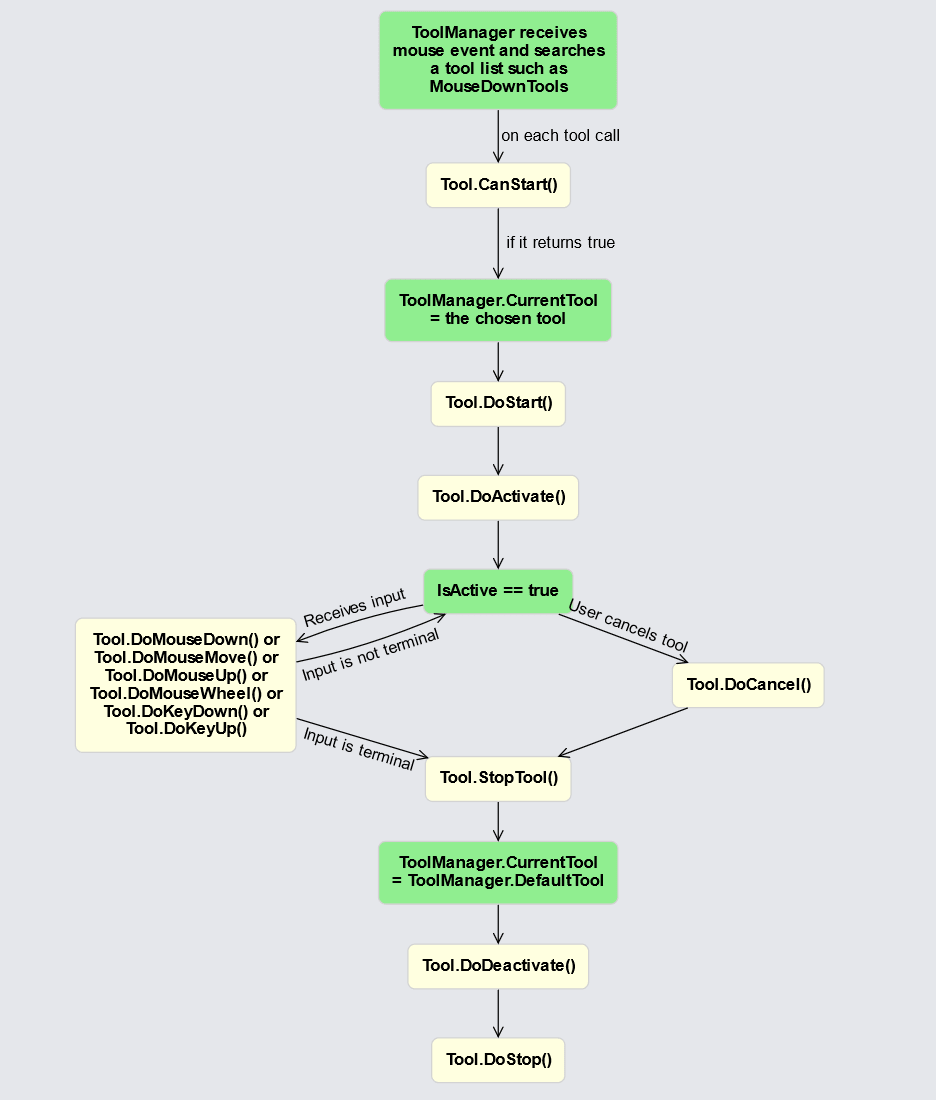
For more information on how these specific functions work, see the Tool documentation.
Tools and Adornments
Adornments are used for more than indicating that a Part is selected. Each Tool that is in the ToolManager.MouseDownTools list (in other words, any mode-less tool that is started with a mouse-down or finger-down event) gets the opportunity to add its own Adornments for its own purposes when a Part is selected.
ResizingTool
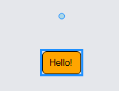
When a Part is resizable, the ResizingTool adds an Adornment containing eight resize handles, four at the corners and four at the middles of the sides.
If you want to let the user resize the whole node, just set Part.Resizable to true. In this case resizing will set the Node's GraphObject.DesiredSize.
  diagram.Add(
    new Node("Auto") { Resizable = true }
      .Add(
        new Shape("RoundedRectangle") { Fill = "orange" },
        new TextBlock("Hello!") { Margin = 5 }
      )
  );
  diagram.CommandHandler.SelectAll();
If you want the user to resize a particular object within the node, you need to name that element and assign Part.ResizeElementName. Resizing will set the Part.ResizeElement's GraphObject.DesiredSize, in this case the Shape's DesiredSize.
  diagram.Add(
    new Node("Vertical") {
        Resizable = true, ResizeElementName = "SHAPE",  // resize the Shape, not the Node
        SelectionElementName = "SHAPE"
      }
      .Add(
        new Shape("RoundedRectangle") {
            Name = "SHAPE", Fill = "orange",
            Width = 50, Height = 30
          },
        new TextBlock("Hello!") { Margin = 3 }
      )
  );
  diagram.CommandHandler.SelectAll();
You can limit the minimum and maximum size for the resized object by setting GraphObject.MaxSize and GraphObject.MinSize. Note that these GraphObject properties are set on the Part.ResizeElement, not on the Part itself.
  diagram.Add(
    new Node("Vertical") {
        Resizable = true, ResizeElementName = "SHAPE",
        SelectionElementName = "SHAPE"
      }
      .Add(
        new Shape("RoundedRectangle") {
            Name = "SHAPE", Fill = "orange",
            Width = 50, Height = 30,
            // limit size by setting or binding MaxSize and/or MinSize
            MaxSize = new Size(100, 40), MinSize = new Size(20, 20)
          },
        new TextBlock("Hello!") { Margin = 3 }
      )
  );
  diagram.CommandHandler.SelectAll();

You can also cause resizing to be multiples of a given size by setting Part.ResizeCellSize.
  diagram.Add(
    new Node("Vertical") {
        Resizable = true, ResizeElementName = "SHAPE",
        ResizeCellSize = new Size(10, 10),  // new size will be multiples of ResizeCellSize
        SelectionElementName = "SHAPE"
      }
      .Add(
        new Shape("RoundedRectangle") {
            Name = "SHAPE", Fill = "orange",
            Width = 50, Height = 30,
            MaxSize = new Size(100, 40), MinSize = new Size(20, 20)
          },
        new TextBlock("Hello!") { Margin = 3 }
      )
  );
  diagram.CommandHandler.SelectAll();
When an object is resizable, it is commonplace to try to remember the new size by updating the model data, so that it can be saved and loaded later. This can be accomplished with a TwoWay Binding on the GraphObject.DesiredSize property. But note that the binding needs to be on the actual GraphObject that is resized, not on the whole Node. In this case, because the Part.ResizeElementName is referring to a Shape, that means the binding needs to be on the Shape.
  diagram.Add(
    new Node("Vertical") {
        Resizable = true, ResizeElementName = "SHAPE",
        SelectionElementName = "SHAPE"
      }
      .Add(
        new Shape("RoundedRectangle") {
            Name = "SHAPE", Fill = "orange",
            Width = 50, Height = 30
          }
          .Bind("DesiredSize", "Size", Size.Parse, Size.Stringify),
        new TextBlock("Hello!") { Margin = 3 }
      )
  );
  diagram.CommandHandler.SelectAll();
You can customize the resize handles by setting Part.ResizeAdornmentTemplate. For example, to allow the user to only change the width of a Shape in a Node, the Adornment should have only two resize handles: one at the left and one at the right. The Adornment is implemented as a Spot Panel that surrounds a Placeholder, representing the adorned Shape, with two rectangular blue Shapes, each representing a handle. There is also a TextBlock placed above the adorned shape showing the shape's current width.
  diagram.Add(
    new Node("Vertical") {
        SelectionAdorned = false,  // don't show selection Adornment
        Resizable = true, ResizeElementName = "SHAPE",
        ResizeAdornmentTemplate =  // specify what resize handles there are and how they look
          new Adornment("Spot")
            .Add(
              new Placeholder(),  // takes size and position of adorned object
              new Shape("Circle") {  // left resize handle
                  Alignment = Spot.Left, Cursor = "col-resize",
                  DesiredSize = new Size(9, 9), Fill = "lightblue", Stroke = "dodgerblue"
                },
              new Shape("Circle") {  // right resize handle
                  Alignment = Spot.Right, Cursor = "col-resize",
                  DesiredSize = new Size(9, 9), Fill = "lightblue", Stroke = "dodgerblue"
                },
              new TextBlock {  // show the width as text
                  Alignment = Spot.Top, AlignmentFocus = new Spot(0.5, 1, 0, -2),
                  Stroke = "dodgerblue"
                }
                .BindElement("Text", "AdornedObject", shp => {
                    return (shp as Shape).NaturalBounds.Width.ToString("N2");
                  }
                )
            )
      }
      .Add(
        new Shape("RoundedRectangle") {
            Name = "SHAPE", Fill = "orange",
            Width = 50, Height = 30,
            MaxSize = new Size(100, 40), MinSize = new Size(20, 20)
          },
        new TextBlock("Hello!") { Margin = 3 }
      )
  );
  diagram.CommandHandler.SelectAll();
Note also that because Part.SelectionAdorned is false, there is no blue rectangle default selection adornment.
There are examples custom resizing tools defined in the samples and extensions directories: Resize Multiple Tool (in Floor Plan Editor), Lane Resizing Tool (in Swim Lanes), and Lane Resizing Tool (in Swim Lanes Vertical).
RotatingTool
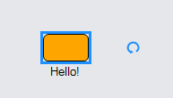
When a Part is rotatable, the RotatingTool adds an Adornment containing one rotate handle a short distance from the object at the object's angle. Since the default GraphObject.Angle is zero, the rotate handle typically starts to the right of the object.
If you want to let the user rotate the whole node, just set Part.Rotatable to true. Rotating will set the Node's GraphObject.Angle.
  diagram.Add(
      new Node("Auto") { Rotatable = true }
        .Add(
          new Shape("RoundedRectangle") { Fill = "orange" },
          new TextBlock("Hello!") { Margin = 5 }
        )
    );
    diagram.CommandHandler.SelectAll();
If you want the user to rotate a particular object within the node, you need to name that object and assign Part.RotateElementName. Rotating will set the Part.RotateElement's GraphObject.Angle, in this case the Shape's angle.
  diagram.Add(
    new Node("Vertical") {
        Rotatable = true, RotateElementName = "SHAPE",  // rotate the Shape, not the Node
        LocationSpot = Spot.Center, LocationElementName = "SHAPE",
        SelectionElementName = "SHAPE"
      }
      .Add(
        new Shape("RoundedRectangle") {
          Name = "SHAPE", Fill = "orange",
          Width = 50, Height = 30
        },
        new TextBlock("Hello!") { Margin = 3 }
      )
  );
  diagram.CommandHandler.SelectAll();

When an object is rotatable, it is commonplace to try to remember the new angle by updating the model data, so that it can be saved and loaded later. This can be accomplished with a TwoWay Binding on the GraphObject.Angle property. But note that the binding needs to be on the actual GraphObject that is rotated, not on the whole Node. In this case, because the Part.RotateElementName is referring to a Shape, that means the binding needs to be on the Shape.
  diagram.Add(
    new Node("Vertical") {
        Rotatable = true, RotateElementName = "SHAPE",
        LocationSpot = Spot.Center, LocationElementName = "SHAPE",
        SelectionElementName = "SHAPE"
      }
      .Add(
        new Shape("RoundedRectangle") {
            Name = "SHAPE", Fill = "orange",
            Width = 50, Height = 30
          }
          .BindTwoWay("Angle"),
        new TextBlock("Hello!") { Margin = 3 }
      )
  );
  diagram.CommandHandler.SelectAll();
Another common customization is to position the rotate handle above the object when it is not rotated, i.e. when its GraphObject.Angle is zero. This is accomplished by setting RotatingTool.HandleAngle to 270.
  diagram.Add(
    new Node("Auto") { Rotatable = true, LocationSpot = Spot.Center }
      .Add(
        new Shape("RoundedRectangle") { Fill = "orange" },
        new TextBlock("Hello!") { Margin = 5 }
      )
  );
  diagram.ToolManager.RotatingTool.HandleAngle = 270;
  diagram.CommandHandler.SelectAll();
You can customize the rotate handle by setting Part.RotateAdornmentTemplate.
  diagram.Add(
    new Node("Vertical") {
        SelectionElementName = "SHAPE",
        Rotatable = true, RotateElementName = "SHAPE",
        RotateAdornmentTemplate =  // specify appearance of rotation handle
          new Adornment { LocationSpot = Spot.Center }
            .Add(
              new Shape("BpmnActivityLoop") {
                Width = 12, Height = 12, Cursor = "pointer",
                Background = "transparent", Stroke = "dodgerblue", StrokeWidth = 2
              }
            )
      }
      .Add(
        new Shape("RoundedRectangle") {
          Name = "SHAPE", Fill = "orange",
          Width = 50, Height = 30
        },
        new TextBlock("Hello!") { Margin = 3 }
      )
  );
  diagram.CommandHandler.SelectAll();
There are example custom rotating tools defined in the samples and extensions directories: Rotate Multiple Tool (in Floor Plan Editor) and Horizontal Text Rotating Tool (in Seating Chart).
RelinkingTool
When a Link is Link.RelinkableFrom and/or Link.RelinkableTo, the RelinkingTool adds one or two Adornments, a diamond at each relinkable end of a selected link. The user can drag a relinking handle to reconnect that end of the link to another port.
The RelinkingTool will automatically update the relationships between the nodes/ports, both in the diagram and in the model. No Bindings are needed for such model updates.
  diagram.NodeTemplate =
    new Node("Auto")
      .Add(
        new Shape { Fill = "lightgray", PortId = "", FromLinkable = true, ToLinkable = true },
        new TextBlock { Margin = 5 }.Bind("Text", "Key")
      );

  diagram.LinkTemplate =
    new Link { RelinkableFrom = true, RelinkableTo = true }
      .Add(
        new Shape(),
        new Shape { ToArrow = "Standard" }
      );

  diagram.Model =
    new MyModel {
      NodeDataSource = new List<NodeData> {
        new NodeData { Key = "Alpha" }, new NodeData { Key = "Beta" },
        new NodeData { Key = "Gamma" }, new NodeData { Key = "Delta" }
      },
      LinkDataSource = new List<LinkData> {
        new LinkData { Key = "A-D", From = "Alpha", To = "Delta" }
      }
    };

  diagram.ToolManager.RelinkingTool.PortGravity = 20;
  diagram.Select(diagram.FindLinkForKey("A-D"));
The relinking handles can be customized by setting RelinkingTool.FromHandleArchetype and RelinkingTool.ToHandleArchetype. At the current time they cannot be customized by setting a property on the Link.
You can limit which pairs of ports between which the user may draw new links or reconnect existing links. This topic is covered by Link Validation.
LinkReshapingTool
When a Link is Part.Reshapable, the LinkReshapingTool adds an Adornment with several reshape handles at the interior points of a selected link's route. When the user drags a reshape handle, the route of the Link, held by Link.Points, is modified.
When a link is reshapable, it is commonplace to try to remember the new route by updating the link data in the GraphLinksModel, so that it can be saved and loaded later. This can be accomplished with a TwoWay Binding on the Link.Points property.
  diagram.NodeTemplate =
    new Node("Auto")
      .Bind("Location", "Loc", Point.Parse)
      .Add(
        new Shape { Fill = "lightgray"},
        new TextBlock { Margin = 5 }.Bind("Text", "Key")
      );

  diagram.LinkTemplate =
    new Link { Reshapable = true, Routing = LinkRouting.Orthogonal }
      .BindTwoWay("Points")  // TwoWay Binding of Link.Points
      .Add(
        new Shape(),
        new Shape { ToArrow = "Standard" }
      );

  diagram.Model =
    new MyModel {
      NodeDataSource = new List<NodeData> {
        new NodeData { Key = "Alpha", Loc = "0 0" },
        new NodeData { Key = "Beta", Loc = "200 50" }
      },
      LinkDataSource = new List<LinkData> {
        new LinkData { Key = "A-B", From = "Alpha", To = "Beta" }
      }
    };

  diagram.Select(diagram.FindLinkForKey("A-B"));
The reshape handles are small blue squares. The reshape handles can be customized by setting LinkReshapingTool.HandleArchetype. At the current time they cannot be customized by setting a property on the Link.
By setting Link.Resegmentable to true, users can add or remove segments from links. The resegmenting handles are even smaller blue diamonds at the middle of each segment. When the user drags a resegmenting handle, a new segment is inserted into the link's route. For orthogonal links, two new segments are introduced in order to maintain orthogonality. When the user reshapes the link so that adjacent segments are co-linear (or nearly so), the segment(s) are removed from the route.
  diagram.NodeTemplate =
    new Node("Auto")
      .Bind("Location", "Loc", Point.Parse)
      .Add(
        new Shape { Fill = "lightgray" },
        new TextBlock { Margin = 5 }.Bind("Text", "Key")
      );

  diagram.LinkTemplate =
    new Link { Reshapable = true, Resegmentable = true, Routing = LinkRouting.Orthogonal }
      .BindTwoWay("Points")  // TwoWay Binding of Link.Points
      .Add(
        new Shape(),
        new Shape { ToArrow = "Standard" }
      );

  diagram.Model =
    new MyModel {
      NodeDataSource = new List<NodeData> {
        new NodeData { Key = "Alpha", Loc = "0 0" },
        new NodeData { Key = "Beta", Loc = "200 50" }
      },
      LinkDataSource = new List<LinkData> {
        new LinkData { Key = "A-B", From = "Alpha", To = "Beta" }
      }
    };

  diagram.Select(diagram.FindLinkForKey("A-B"));
The resegmenting handles can be customized by setting LinkReshapingTool.MidHandleArchetype. At the current time they cannot be customized by setting a property on the Link. Also at the current time resegmenting is not supported on Bezier-curved links.
If you want your users to be able to reshape Shape geometries that are not Link paths, there is the Geometry Reshaping Tool used by the Polygon Drawing and Freehand Drawing samples in the extensions directory. It is defined in a separate file that you can load into your app.
Tools and Tool Parts
Some tools make use of special Parts that they add to the "Tool" Layer as feedback during the tool's operation.
DragSelectingTool
The DragSelectingTool uses the DragSelectingTool.Box to show the area in which it will select Parts. Normally this is a simple magenta rectangular shape. You can change it. For example here is a drag-selecting box that is in the shape of a blue-outlined cloud.
  diagram.NodeTemplate =
    new Node("Auto")
      .Bind("Location", "Loc", Point.Parse)
      .Add(
        new Shape { Fill = "lightgray" },
        new TextBlock { Margin = 5 }.Bind("Text", "Key")
      );

  diagram.ToolManager.DragSelectingTool.IsPartialInclusion = true;
  diagram.ToolManager.DragSelectingTool.Box =
    new Part { LayerName = "Tool" }
      .Add(
        new Shape("Cloud") { Name = "SHAPE", Fill = null, Stroke = "dodgerblue", StrokeWidth = 2 }
      );

  diagram.Model =
    new MyModel {
      NodeDataSource = new List<NodeData> {
        new NodeData { Key = "Alpha", Loc = "0 0" },
        new NodeData { Key = "Beta", Loc = "200 50" }
      },
      LinkDataSource = new List<LinkData> {
        new LinkData { From = "Alpha", To = "Beta" }
      }
    };
Note that the DragSelectingTool expects that the object in the "box" to be resized is named "SHAPE". The object should be rectangular too, or else the user might be misled by the area in which parts will be selected. Finally note also that the box is not an Adornment because it does not "adorn" any Part. It is just an unbound Part that is used temporarily by the DragSelectingTool.
There are examples of in-the-background-dragging tools defined in the extensions directory: Realtime Drag Selecting Tool, Drag Creating Tool, and Drag Zooming Tool. Each is defined in a separate file that you can load into your app.
LinkingTool and RelinkingTool
The linking tools, LinkingTool and RelinkingTool, inherit from a base class, LinkingBaseTool, that uses several Parts: a temporary Link and temporary "to" and "from" Nodes.
To customize the appearance and behavior of the temporary Link that is shown during a linking operation, you need to modify or replace the LinkingBaseTool.TemporaryLink. The default temporary link is a blue line with a standard arrowhead. The originating port and the potential target port are shown by the LinkingBaseTool.TemporaryFromNode and LinkingBaseTool.TemporaryToNode. The default temporary ports are magenta rectangles.
  diagram.NodeTemplate =
    new Node("Spot")
      .Bind("Location", "Loc", Point.Parse)
      .Add(
        new Shape("RoundedRectangle") {
          Width = 100, Height = 40, Fill = "lightyellow",
          PortId = "", FromLinkable = true, ToLinkable = true, Cursor = "pointer"
        },
        new TextBlock().Bind("Text", "Key")
      );

  diagram.ToolManager.LinkingTool.TemporaryLink =
    new Link { LayerName = "Tool" }
      .Add(
        new Shape() { Stroke = "red", StrokeWidth = 2, StrokeDashArray = new float[] { 4, 2 } }
      );

  var tempfromnode =
    new Node { LayerName = "Tool" }
      .Add(
        new Shape("RoundedRectangle") {
          Stroke = "chartreuse", StrokeWidth = 3, Fill = null,
          PortId = "", Width = 1, Height = 1
        }
      );
  diagram.ToolManager.LinkingTool.TemporaryFromNode = tempfromnode;
  diagram.ToolManager.LinkingTool.TemporaryFromPort = tempfromnode.Port;

  var temptonode =
    new Node { LayerName = "Tool" }
      .Add(
        new Shape("RoundedRectangle") {
          Stroke = "cyan", StrokeWidth = 3, Fill = null,
          PortId = "", Width = 1, Height = 1
        }
      );
  diagram.ToolManager.LinkingTool.TemporaryToNode = temptonode;
  diagram.ToolManager.LinkingTool.TemporaryToPort = temptonode.Port;

  diagram.Model =
    new MyModel {
      NodeDataSource = new List<NodeData> {
        new NodeData { Key = "Alpha", Loc = "0 0" },
        new NodeData { Key = "Beta", Loc = "200 50" },
        new NodeData { Key = "Gamma", Loc = "400 0" },
      },
      LinkDataSource = new List<LinkData> { }  // start off with no links
    };
You will notice that the nodes (actually the ports) are highlighted by the temporary nodes in chartreuse and cyan. The temporary link is a dashed red line without an arrowhead.
If your app also supports relinking you will probably want to do the same customizations on the RelinkingTool.
There are examples of linking tools defined in the samples and extensions directories: Polyline Linking Tool, Messaging Tool (in Sequence Diagram), and Custom Linking Tool (in Grafcet Diagram)
Custom Tools
The GoDiagram samples and extensions demonstrate a number of custom tools, including:
- Resize Multiple Tool (in Floor Plan Editor)
- Lane Resizing Tool (in Swim Lanes)
- Lane Resizing Tool (in Swim Lanes Vertical)
- Rotate Multiple Tool (in Floor Plan Editor)
- Horizontal Text Rotating Tool (in Seating Chart)
- Geometry Reshaping Tool used by the Polygon Drawing Freehand Drawing
- Realtime Drag Selecting Tool
- Drag Creating Tool
- Drag Zooming Tool
- Polyline Linking Tool
- Messaging Tool (in Sequence Diagram)
- Custom Linking Tool (in Grafcet Diagram)